
USE OF CHANNELIZATION WITH GATES
At many crossings, drivers can cross the centerline pavement marking and drive around a gate with little difficulty. The number of crossing gate violations can be reduced by restricting driver access to the opposing lanes. Highway authorities have implemented various median separation devices, which have shown a significant reduction in the number of vehicle violations at crossing gates.(30)
Various styles of median treatments include barrier wall systems, wide raised medians, and mountable raised curb systems. In addition to discouraging crossing gate evasion, such treatments may be used to restrict left-turns across the median to and from driveways or minor streets adjacent to the crossing thus reducing conflicting vehicular turning movements in the crossing vicinity. The benefits of installing channelization should be considered along with possible adverse effects on local access and circulation as well as the potential for a road user to strike the barrier. Medians and traffic channelizing devices need to be kept out of the path of turning vehicles to avoid being struck. The median should be designed to allow vehicles to make left turns or U-turns through the median where appropriate, based on engineering judgment and evaluation.
It should be noted that median treatments meeting the requirements of Appendix A of 49 CFR Part 222 are considered supplemental safety measures by FRA for use in a quiet zone (see Quiet Zones).(5)
Barrier Wall Systems
Concrete barrier walls and guardrails prevent drivers from crossing into opposing lanes throughout the length of the installation. In this sense, they are the most effective deterrent to crossing gate violations; however, the road should be wide enough to accept the width of the barrier and the appropriate end treatment. Sight restrictions for vehicles with low driver eye heights and any special needs for emergency vehicles to make a U-turn maneuver should be considered (but not for circumventing the traffic control devices at the crossing). To increase the effectiveness of barrier wall systems, they should extend from the crossing to a length of 100 feet.
Wide Raised Medians
Curbed medians typically range in width from 4 to 16 feet, although wider medians may be present along divided highways. Although they do not present a true barrier, wide medians can be nearly as effective because a driver would have significant difficulty attempting to drive across to the opposing lanes. The impediment becomes more formidable as the width of the median increases.
Drawbacks to implementing wide, raised medians include the availability of sufficient ROW and the maintenance of surface and/or landscape. Additions such as trees, flowers, and other vegetation higher than 3 feet above the roadway can restrict drivers' views of approaching trains. Maintenance can be expensive, depending on the treatment of the median. Limitation of access can cause property owner complaints, particularly for businesses.
Non-Mountable (Non-Traversable) Curb Islands
Non-mountable curb islands are typically 6 to 9 inches in height and at least 2 feet wide and may have flexible, reflectorized tubular delineators or vertical panels. Drivers have significant difficulty attempting to violate these types of islands because the 6- to 9-inch heights cannot be easily mounted and crossed.
Some disadvantages should be considered. The road must be wide enough to accommodate a 2-foot median. The increased crash potential should be evaluated. AASHTO recommends that special attention be given to high visibility if such a narrow device is used in higher-speed (greater than 40 mph) environments.(22) Care should be taken to assure that an errant vehicle cannot bottom-out and protrude into the oncoming traffic lane. Sight restrictions for low driver eye heights should be considered if tubular delineators or vertical panels are installed. Access requirements should be fully evaluated, particularly allowing emergency vehicles to cross opposing lanes (but not for circumventing the traffic control devices at the crossing). Paint and reflective beads should be applied to the curb for night visibility.
The State of Illinois has developed a standard that uses a combination of mountable and non-mountable curbs to provide a wide, raised median with escape zones both in the median, as well as to the shoulder (see Figure 36). This treatment is intended to allow vehicles trapped on the tracks due to queued traffic to maneuver from the crossing to a safe area in the median or on the shoulder.
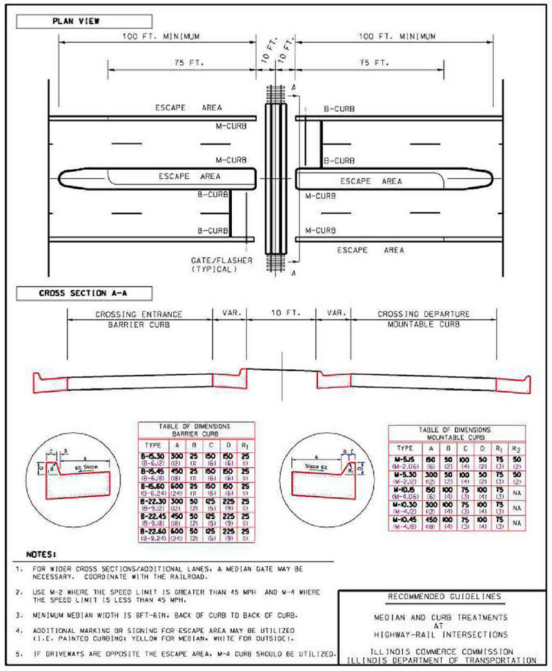
Source: Illinois Department of Transportation, Bureau of Local Roads and Streets Manual, Illinois DOT, Revised June 2018, Mountable Raised Curb Systems.
Mountable Raised Curb Systems (Traffic Separators)
Mountable raised curb systems or "traffic separators," with flexible tubular delineators or vertical panels present drivers with a visual impediment to crossing to the opposing traffic lane (see Figure 37). The curbs are no more than 6 inches in height, less than 12 inches in width, and built with a rounded design to create minimal deflection upon impact. When used together, the mountable raised median and tubular markers or vertical panels discourage passage. These systems are designed to allow emergency vehicles to cross opposing lanes (but not to circumvent the traffic control devices at the crossing). Usually, such a system can be placed on existing roads without the need to widen them.
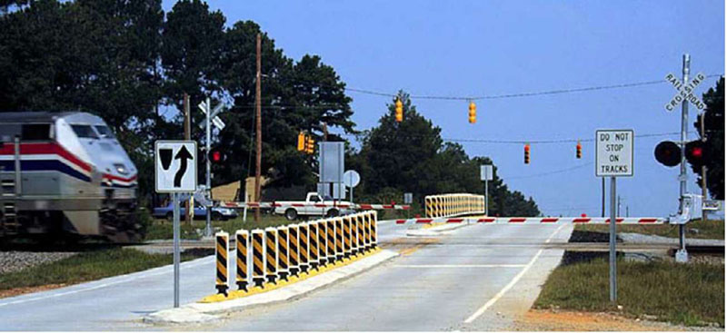
Source: USDOT, Federal Railroad Administration, Research Results 10-03 (Washington, DC, June 2010).
Because mountable curbs are intended to allow emergency vehicles to cross and are designed to deflect errant vehicles, they also are the easiest of all the barriers and separators to violate. Large, formidable tubular delineators or vertical panels will inhibit most drivers. Care should be taken to ensure that the system can withstand normal traffic conditions and that retroreflective surfaces are maintained in good condition for night-time visibility. Additional guidance is found in the MUTCD Section 3B.23.
These mountable raised curb systems have proven effective and are relatively inexpensive compared to treatments which require roadway reconstruction.(30) These traffic separators are installed along the centerline of roadways, in most cases extending approximately 70 to 100 feet from the crossing. They prevent motorists from crossing lanes to "run around" activated crossing gates. The separators consist of prefabricated, mountable islands made of a composite material. Attached to the islands are vertical panels or tubular delineators with retroreflective surfaces for better visibility at night. The vertical panels or tubular delineator are flexible, yet securely anchored allowing them to return to their original positions if struck by a vehicle.
PREEMPTION OF TRAFFIC SIGNALS
Because a downstream traffic signal may cause traffic to back up toward and/or through a grade crossing, it is essential that provisions be made to allow traffic to clear from the track area prior to train arrival. This is accomplished by means of traffic signal "preemption"–the normal sequence of operation is suspended and a programmed alternative sequence takes over. A preemption sequence compatible with railroad crossing active traffic control devices is extremely important to provide safe vehicular and pedestrian movements. Such preemption serves to ensure that the actions of these separate traffic control devices complement rather than conflict with each other.
The MUTCD (see Section 8C.09) indicates that grade crossings with active warning devices (such as flashing-light signals with or without gates) located within 200 feet of an intersection or midblock location controlled by a traffic signal should be interconnected with the nearby intersection's traffic control system such that the railroad devices can send a preemption call to the highway signals upon detection of an approaching train. The MUTCD also indicates that coordination with the flashing-light signal system, queue detection, or other alternatives should be considered for traffic signals located further than 200 feet, while taking into consideration traffic volumes, highway vehicle mix, highway vehicle and train approach speeds, frequency of trains, and queue lengths.
At a signalized intersection located within 200 feet or less of a crossing, where the intersection traffic control signals are preempted by the approach of a train, all movements from the signalized intersection approaching the crossing should be prohibited during the signal preemption sequences.
A blank-out or Changeable Message Signs (CMS) and/or appropriate highway traffic control signal indication (such as a red arrow indication where a left-turn bay is present) or other similar type sign may be used to prohibit turning movements toward the highway-rail crossing during preemption. These signs may include supplemental blank-out legend which display the word or symbol for trains or LRT.
To understand the concept of preemption, the practitioner should be familiar with two fundamental terms which are depicted in Figure 38. The Clear Storage Distance (CSD) is the space between the crossing and a downstream intersection where vehicles may safely queue and the Minimum Track Clearance Distance (MTCD) is the area which must be clear of roadway vehicles to avoid a collision with a train. These are defined as follows:
Clear Storage Distance. Per the MUTCD definitions, (Part 1A.13), the distance available for vehicle storage measured between 6 feet from the rail nearest the intersection to the intersection stop line or the normal stopping point on the highway. At skewed crossings and intersections, the 6-foot distance is measured perpendicular to the nearest rail either along the center line or edge line of the highway, as appropriate to obtain the shorter distance. Where exit gates are used, the distance available for vehicle storage is measured from the point where the rear of the vehicle would be clear of the exit gate arm. In cases where the exit gate arm is parallel to the track(s) and is not perpendicular to the highway, the distance is measured either along the center line or edge line of the highway, as appropriate, to obtain the shorter distance.
Minimum Track Clearance Distance. For standard two-quadrant warning devices, the MTCD is the length along a highway at one or more railroad tracks or LRT tracks. Where flashing-light signals with automatic gates are used, the MTCD is measured from the portion of the gate arm farthest from the near rail. Where flashing-light signals are used without automatic gates, the MTCD is measured from the stop line. Where passive traffic control devices are used, the MTCD is measured from the stop line. Where the roadway is not paved, the MTCD is measured from 10 feet perpendicular to the near rail. The MTCD ends 6 feet beyond the track(s) measured perpendicular to the near rail. The MTCD ends 6 feet beyond the track(s) measured perpendicular to the far rail, along the center line or edge line of the highway, as appropriate, to obtain the longer distance. For Four-Quadrant Gate systems (where exit gates are used), the MTCD is extended to the point where a vehicle is clear of the exit gate arm. In cases where the exit gate arm is parallel to the track(s) and is not perpendicular to the highway, the distance is measured either along the center line or edge line of the highway, as appropriate, to obtain the longer distance.
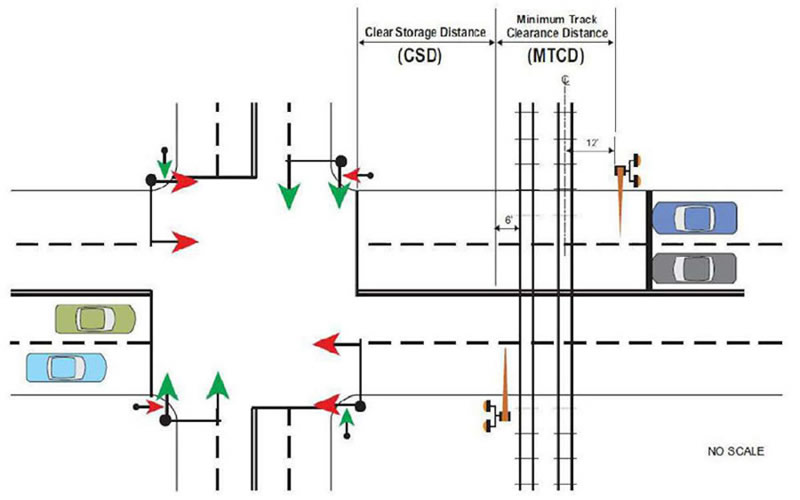
Source: AECOM, Inc.
Excerpts from ITE Recommended Practice on Preemption of Traffic Signals Near Railroad Crossings
It is beyond the scope of this Handbook to incorporate all specifics regarding preemption of traffic signals near crossings. The following material has been synthesized from the recently updated (2019) ITE Proposed Recommended Practice: Preemption of Traffic Signals Near Railroad Crossings; practitioners involved with implementation of preemption should use the full document as a reference.(3)
- Where a signalized highway intersection exists in close proximity to a railroad crossing and either the crossing is impacted by queues from the intersection or the intersection is impacted by queues from the crossing, the railroad signal control equipment and the traffic control signal control equipment should be interconnected, and the normal operation of the traffic signals controlling the intersection should be preempted to operate in a special control mode when trains are approaching (MUTCD). A preemption sequence compatible with railroad crossing active traffic control devices is extremely important to provide safe vehicular and pedestrian movements. Such preemption serves to ensure that the actions of these separate traffic control devices complement, rather than conflict with, each other.
- Where a signalized highway intersection is not in close proximity to a railroad crossing, coordination between the traffic control signal and railroad warning devices may still be necessary. Coordination is essential where vehicular queues periodically or routinely extend onto the railroad crossing, and may include preemption or queue management techniques such as queue detection, queue-cutter signals, or dynamic control of traffic control signal timing plans to eliminate queuing on the tracks.
- It is important that the traffic engineer responsible for designing the preemption system understand with sufficient detail how the traffic control signal controller unit operates in response to a call for a preemption sequence. The traffic engineer should also ensure that the traffic control signal controller unit is capable of performing all of the functions required under all possible rail movements in order to provide proper functioning of the preemption operation. Rail operations such as multiple train movements, stops within the approach circuitry, and re-starts of stopped trains within the approach circuitry can result in insufficient queue clearance time from the train detection circuitry. The traffic engineer should consult with railroad personnel responsible for railroad signal design and operations to ensure that appropriate equipment is specified and that both highway and railroad signal installations operate properly and with full compatibility. Continuous cooperation between highway and railroad personnel is essential for safe operation. Information concerning the type of railroad signal equipment that can be used is available from the operating railroad and from the AREMA Communications and Signal Manual In addition, State and local regulations should be consulted.
When to Preempt
If either of the following conditions is present, careful consideration should be given to interconnecting traffic signals on public and private highways with active warning devices at railroad crossings:
- Highway traffic queues have the potential for extending across a railroad crossing from a nearby highway traffic signal
- Traffic queues from a railroad crossing have the potential to interfere with a nearby highway traffic signal
A railroad crossing equipped with a passive control device may need to be upgraded to an active warning device so that preemption of the traffic control signal can be effectively implemented. Such improvements are particularly important when the tracks are close to the signalized intersection or when certain conditions exist, such as vehicles queuing onto the tracks, high-speed train or highway approaches, tracks in highway medians, steep grades, or traffic that includes school buses or trucks carrying hazardous material.
Traffic Queues Extend Across the Railroad Crossing
If traffic queues extend onto the railroad crossing from a nearby highway traffic signal, then it is essential to provide some means of clearing vehicles off the tracks before a train arrives. Current practice is to consider use of preemption where a traffic signal is within 200 feet of a crossing. However, the MUTCD notes that coordination with the flashing-light system, such as queue detection, should be considered for traffic signals located farther than 200 feet from the crossing. Two-hundred feet is an approximation of the distance within which traffic queuing is likely to occur. Regardless of the actual distance between the railroad crossing and a traffic signal, preemption or coordination should be considered whenever there is a likelihood that queuing will impact either the railroad crossing or the highway intersection. Factors that could affect queuing include traffic volumes, vehicle mix, train frequency, presence of driveways or unsignalized intersections, and traffic backed up from a nearby downstream intersection.
Long Distances
Where the Clear Storage Distance (CSD) exceeds 200 feet, the likelihood of a queue extending across the tracks should be determined. One or more of the following methods may be used to make this determination:
- Anecdotal Evidence–Highway authority technical staff, police, train operators, or train dispatchers may have observed queuing on the tracks. Anecdotal information may be especially useful to identify time periods of concern or other causative factors which could be verified through subsequent field observation.
- Traffic Engineering Calculations3–For isolated signalized intersections, conventional computations can be developed to estimate queueing based upon vehicle arrival rates, the vehicle mix, and traffic control signal timing. A wide range of commercially available software may be used as well.
- Traffic Simulation Modeling–Intersections located along highly-congested roadway segments or which are operating as part of a coordinated system of signals may be evaluated using traffic simulation software. Simulation software may also help address unusual traffic patterns such as special event traffic.
- Field Observations–Visual queue arrival and dissipation studies may be made during multiple peak travel demand times at the site. Video surveillance equipment may be installed and data recorded during periods of concern. Field observations should consider significant traffic generators which may impact queuing such as shopping centers during peak seasons, schools when they are in session, and sporting events.
3 "Timing of Traffic Signal Preemption at Intersections Near Highway-Rail Grade Crossings," Robert K. Seyfried. ITE 2001 Annual Meeting and Exhibit CD-ROM, ITE, 2001.
Neither the MUTCD 200-foot threshold nor the queue calculation equation is intended to provide a specific distance as the sole criterion for interconnecting railroad and highway signals. Special consideration should be given where upstream signals cause vehicles to arrive in platoons that could result in long queue lengths. Unusual 15-minute peak-period flow rates should be evaluated. For example, where a mix of long slow trains and short fast trains could be present at multi-track crossings, it is possible that a long queue of vehicles may develop at the crossing as a slow, long train passes; subsequently, this long platoon of vehicles could be advancing through the crossing when a fast, short train arrives. Pre-signals and queue cutters may be effective for long distances.
Short Distances
Where the CSD is not sufficient to store the longest vehicle known to use the crossing (the "design vehicle"), or if vehicles regularly queue across the tracks, a pre-signal may be considered. An engineering study should be performed to support this recommendation. Where no crossing gates are present, a pre-signal can discourage design vehicles from stopping in the CSD or in the MTCD.
Additional Preemption Issues
Other issues to consider in the evaluation of the implementation of preemption include the following:
- Trucks and Vehicles Required to Stop by Law–Additional clearance time may be required; if a truck is turning toward the tracks and encounters lowered crossing gates it may be stopped in a position blocking the departure lanes.
- Grades–The presence of an upgrade on the approach will require consideration of additional clearance time, especially for heavy vehicles.
- Crossing Gate Spillback–Even if traffic can clear from the tracks in advance of the arrival of a train, queues may spill back into an adjacent intersection resulting in blockage of movements. Interconnection can be used to address such issues.
- Circular Intersections–Although roundabouts and traffic circles are designed to operate without traffic signals, they may become congested resulting in blockage of a crossing on an approach leg. Mitigation may require installation of a traffic control signal or queue cutter signal.
- Light Rail Crossings–Although gate down (A crossing gate is in the "down" or lowered position when it is horizontal in accordance with the predetermined design from vertical, which is typically 85 to 92 degrees depending on specific gate mechanism adjustment and other factors) times for LRT are relatively short, frequent activations will require that the system be designed to handle the approach of a second train possibly arriving during the preemption sequence for the first train. Also, motion sensing and Constant Warning Time (CWT) devices may not operate properly in electrified systems, and special devices or track circuits will likely be required. Because there is typically little variability in train speeds on LRT tracks, CWT devices are often not necessary.
Preemption Operation Modes
Preemption of traffic signals may be either simultaneous or advance as determined by the diagnostic team. Simultaneous preemption occurs when notification of an approaching train is forwarded to the highway traffic control signal controller unit and the railroad active warning devices at the same time. Advance preemption occurs when notification of an approaching train is forwarded to the traffic control signal controller unit by railroad equipment for a period of time prior to the activation of the railroad active warning devices.
Preemption operation, whether simultaneous or advance, requires the consideration of three fundamental timing parameters:
- Right of Way Transfer Time (RWTT)–The time required to transition into track clearance
- Queue Clearance Time–The time required to clear traffic from the MTCD
- Separation Time–The time between the clearance of the last vehicle and the arrival of a train
The sum of these three parameters is the Maximum Highway Traffic Signal Preemption Time (MPT). It is also the required minimum amount of time from when the preemption interconnection is activated and the time that the train arrives at the crossing.
Simultaneous Preemption Operation
With simultaneous preemption, the railroad warning devices are active for the entire duration of the MPT since both systems are activated simultaneously. In most cases, calculation of the necessary time elements for preemption operation will find that additional warning time from the railroad is necessary. The additional time is specified as Clearance Time, which is added to the minimum warning time.
Simultaneous preemption can be used at locations where the track is located in the center of the preempted intersection or where the CSD is very short and has a short queue clearance time.
Advance Preemption Operation
With advance preemption, the traffic control signal controller begins the preemption sequence for a period before the railroad warning devices are activated. The difference between the MPT and the activation of the railroad warning devices is called the advance preemption time. Where there is a long MPT, advance preemption can reduce the length of time the railroad warning devices operate before the preemption clearance interval begins.
The use of advance preemption requires close coordination between highway agencies and the railroad companies to ensure that all parties fully understand the operation of each other's system. The additional time required to be provided from the railroad signaling system to provide the MPT requirement may result in an increase in cost for the installation and maintenance due to the additional control equipment and complexity of the railroad circuitry.
Interconnection Control Circuits
The approach of a train to a railroad crossing de-energizes the interconnection or sends a message via a fail-safe data communication protocol, which in turn activates the traffic control signal controller preemption sequence. Preemption should be implemented with an interconnection using fail-safe design principles. Types of fail-safe connections include the following:
- Single Break with Supervision–A supervised preemption interconnection incorporates both a normally-open and a normally-closed circuit from the crossing warning system to verify the proper operation of the interconnection.
- Double Break (with or without Supervision)–In lieu of or in addition to supervision, a double break preemption interconnection circuit utilizing two normally-closed circuits that open both the source and return energy circuits may be used.
- Data Communication (IEEE 1570)–This standard utilizes the vital data protocol IEEE 1570. It is a hybrid between Intelligent Transportation Systems (ITS) and rail signaling technologies in which railroad warning devices are considered "vital equipment," and as such are designed using fail-safe principles.
Queue Management
Queue management can be provided through use of Pre-Signals, Queue Cutters, combination Pre-Signal/Queue Cutter installations, or through use of coordinated traffic signals.
- Pre-Signals–As defined by the MUTCD (Section 1A.13), Pre-Signals are "traffic control signal faces that control traffic approaching a grade crossing in conjunction with the traffic control signal faces that control traffic approaching a highway-highway intersection beyond the tracks." Pre-signals can be used to stop vehicular traffic before the railroad crossing in cases where the CSD, measured between 6 feet from the rail nearest the intersection to the intersection stop line or the normal stopping point on the highway) is 50 feet or less (or 75 feet if the design vehicle is longer). Pre-signals can also be used where the CSD is as much as 200 to 250 feet, depending on vehicle lengths. In this case, it is not expected that all vehicles will be cleared from the CSD; only from the MTCD. (Note: Where the CSD is one design vehicle length or less, relocating the stop line upstream of the crossing may be sufficient to control queuing without the need for a pre-signal.)
- Queue-Cutter Signals–In cases where the crossing is located farther than 450 to 500 feet (depending on vehicle lengths) from the highway intersection, the use of preemption with or without a pre-signal can lead to very long preemption times and approach circuits so that all vehicles downstream from the crossing can move and allow the crossing to clear which may be impractical. One remedy to consider in this case is a queue-cutter signal. A queue-cutter is a traffic control signal which only controls traffic approaching a crossing and is operated independently of other traffic signals in the vicinity. The concept of operation of a queue-cutter is to hold traffic ("cut the queue") upstream from a crossing before a queue caused by a downstream traffic control signal or other roadway congestion can grow long enough to back up into the crossing. Queue-cutter signal operation may be based on downstream queue loop detectors, timed operations, or a combination of the two.
- Combination Pre-Signal/Queue Cutter Signal–Queue-cutter signals are used where the CSD exceeds 450 to 500 feet (depending on vehicle lengths) because room is needed downstream from the crossing to detect the development of a queue as well as store vehicles (including a design vehicle) which continue to cross until the approaching traffic is stopped. Queue cutters may also be considered where the CSD is between 200 and 450 feet if they operate in a hybrid mode as a combination pre-signal and queue-cutter signal. The presence of an effective queue-cutter can eliminate the need for preemption of the downstream traffic signal. The suggested distances are guidelines and can vary depending on traffic volumes, peaking characteristics, arrival patterns, and other factors.
- Coordinated Traffic Signals–As a variation of queue-cutter signals, traffic control signal coordination may be provided to manage queues along a roadway segment which includes a crossing. Within a network of coordinated traffic signals, the likelihood of queuing within the MTCD can be reduced by providing more green time and capacity at the traffic control signal downstream from a crossing relative to the green time and capacity provided for movements approaching the crossing.
In addition to active traffic control of queuing, there may be locations where use of an active warning sign may be more appropriate. If traffic has the potential to back up from a STOP sign-controlled intersection where signalization is not justifiable, or if traffic occasionally backs up due to special events, an active warning sign activated by time-of-day or queue detection could be provided to remind road users of the risk of stopping on the crossing. Options include use of an active blank-out "DO NOT STOP ON TRACKS" (R8-8) sign or a warning beacon and passive sign including the phrase "WHEN FLASHING" (refer to MUTCD Section 4L.03).
Comparison of Queue Management Techniques
Table 5 summarizes the typical CSD ranges and key operational characteristics of pre-signals, queue cutters, and traffic control signal coordination as used to control queuing near a crossing. The CSD ranges reflect variations in vehicle lengths. Where there is a significant percentage of long vehicles, the higher end of each range should be used. The CSD ranges are guidelines and can vary depending on traffic volumes, speeds, peaking characteristics, arrival patterns, and other factors. It should be noted that the operational parameters and design characteristics of Hybrid Pre-Signal/Queue Cutter signals need to be adapted to site geometric and traffic flow conditions especially regarding placements of signal heads, loop detectors, and pavement markings.
Additional information provided in the ITE Recommended Practice.
As noted in the introduction to the preemption topic, the information presented in the Handbook is intended as an introduction to preemption. The ITE Recommended Practice covers these topics and many more in depth as noted:
- Train Detection
- Interconnection Control Circuits
- Crossings Between Two Signalized Intersections
- Diagonal Intersections
- Pre-Signals Design and Operations
- Queue Cutter Design and Operations
- Preemption Timing Parameters
- Use of Gate Down Circuit
- Preemption Hold Interval
- Exit to Normal Operations
- Pedestrian Signal Indications
- Considerations with Exit Gates
- Case Studies
Table 5. Comparison of Queue Management Devices and Techniques
| Clear Storage Distance | Application | Key Operational Characteristics |
|---|---|---|
| Less than 50-75 fta | Relocated Stop Line with or without Pre-signal |
|
| 50-75 ft to 200-250 fta | Pre-signal |
|
| 200-250 ft to 450-500 fta | Hybrid Pre-signal/ Queue-Cutter |
|
| 450-500 fta or more | Queue-Cutter |
|
| Variable | Coordinated Traffic Signals |
|
aBased upon length of vehicle used as the basis for design.
Pre-Signal and Queue Cutter Design Considerations
This section provides illustrative examples of pre-signal and queue cutter treatments demonstrating various design options. Design considerations for pre-signals include placement of the pre-signal heads, stop line placement, and whether the downstream intersection signal should be modified to limit the visibility of the green indication. For queue cutters, in addition to the placement considerations, the means of operation (with or without detection) and location of the detection zone (if provided) are prime concerns.
The location of pre-signal mast arm poles can be located upstream or downstream from the railroad crossing. In all cases, pre-signal poles should be located to maintain visibility of the railroad flashing-lights. If an existing railroad cantilever exists, and upstream pre-signals are used, the heads may be mounted on the cantilever if permitted by the railroad or regulatory agency. If they are on a separate mount, they should be located to avoid blockage or interference with the visibility of the railroad flashing-lights. Railroad flashing-lights should be located as specified in Chapter 8C of MUTCD. Refer also to AREMA Communications and Signal Manual Parts 3.1.36 and 3.1.37 for additional guidance regarding the location of railroad warning devices.(29)
Traffic control signal faces at the downstream intersection may be equipped with programmable-visibility heads or louvers as appropriate based on an engineering study to minimize road user confusion. The purpose of the signal programmable-visibility heads or louvers is to limit visibility of the downstream signal faces to the area from the intersection stop line to the location of the first vehicle behind the pre-signal stop line. This is to prevent drivers stopped at the railroad crossing stop line from seeing the distant green signal indication which would be displayed during the track clearance interval. An engineering study should be conducted to review the specific site conditions, including the eye heights of drivers of vehicles likely to use the crossing, and establish the final design necessary to meet the visibility requirements.(31)
Where the CSD is greater than that which is typical for a pre-signal, a combination pre-signal/ queue cutter should be considered. In addition to the head placement considerations associated with pre-signal design, queue cutter design should consider whether it is feasible to provide detection as well as the placement of the detection zone. If adequate storage exists such that a detection zone can be provided, an adequate distance beyond the crossing to store additional vehicles which would arrive during the detection, phase change and driver response time, then the queue cutter can operate independent of any downstream signal. On the other hand, if such storage does not exist, then the queue cutter may need to be tied into the downstream signal to be effective (resulting in a hybrid installation). If a hybrid signal is provided, then the detection zone can be placed closer to the crossing because its purpose is purely to determine when the hybrid signal can revert to a green indication.
Relocated Stop Line
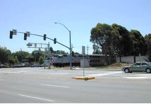
Figure 39 shows placement of the stop line ahead of the grade crossing, in conjunction with use of STOP HERE ON RED (R10-6) and DO NOT STOP ON TRACKS (R8-8) signs. As the CSD is minimal, it was not necessary to use a pre-signal at this location.
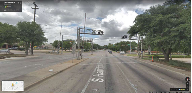
Source: Google Earth V 7.1.7.2602. (September 6, 2016). Hampton Rd near Wright St, Dallas, TX, USA.32°43'31.98"N, 96°51'24.76"W, Eye alt eye level. DirectX2016. Google Earth Pro. [January 30, 2019].
Pre-Signal with Displaced Stop Line
Figure 40 shows where the pre-signal stop line has been placed ahead of the crossing to comply with MUTCD traffic signal visibility requirements. Despite the long distance to both the crossing and the downstream intersection, there is a high degree of driver compliance with the pre-signal at this location.
Source: Brent Ogden.
Pre-Signal Mounted Downstream from Crossing
Figure 41 shows a pre-signal mounted downstream from a single-track crossing. Placement of the pre-signal beyond the rail track allows placement of the stop line and crossing gates close to the track. The downstream signal has louvered heads on the green indications (see inset photo) to avoid confusion with the pre-signal red indication.
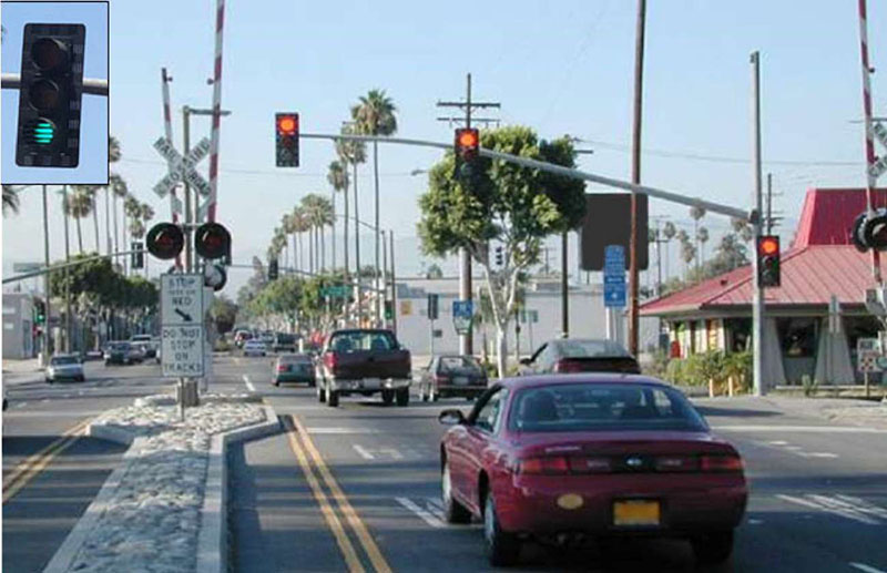
Source: Brent Ogden.
Pre-Signal Mounted on Railroad Cantilever
Figure 42 shows a pre-signal mounted on the railroad cantilever. The CSD to E. Lakewood Blvd. is about 175 feet. Note the non-conflicting placement of flashing-light warning signals and traffic signal heads mounted on the railroad cantilever.
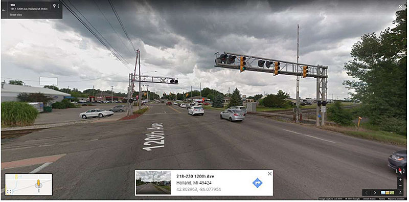
Source: Google Earth V 7.1.7.2602. (September 6, 2016). Lakewood Ave near Garden Ave, Holland, MI, USA.42°48'17.52"N, 86°04'26.42"W, Eye alt eye level. DirectX 2016. Google Earth Pro. [January 30, 2019].
Queue Cutter
Figure 43 shows a queue cutter which utilizes detection loops. The CSD at this location is about 340 feet, and the detection zone is located about 100 feet downstream from the crossing which provides enough storage for vehicles which arrive during the detection–phase change–driver reaction time interval. Note that the primary queue cutter signal heads are located downstream from the crossing to assure the MUTCD visibility criteria is met; however, there are additional pole-mounted heads at the stop line along with a STOP HERE ON RED (R10-6) sign.
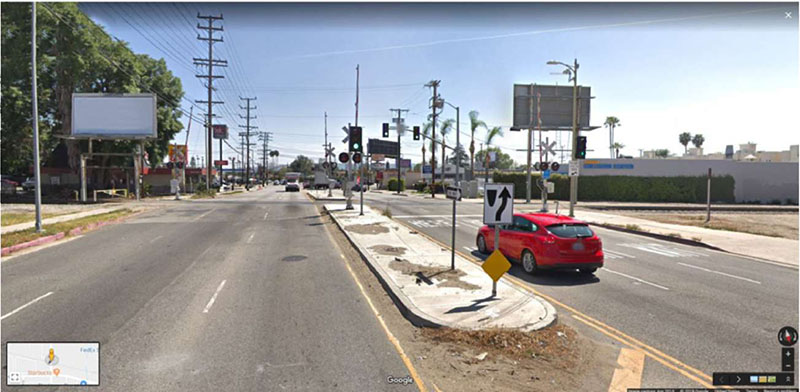
Source: Google Earth V 7.1.7.2602. (September 6, 2016). Balboa Blvd near Roscoe Blvd, Los Angeles, CA,, USA.34°13'20.42"N, 118°30'08.87"W, Eye alt eye level. DirectX 2016. Google Earth Pro. [January 30, 2019].
Queue Prevention Strategies
At highway-rail crossings located near signalized intersections, where traffic congestion precludes using standard traffic control signal preemption, traffic control strategies may be used to prevent queues from extending back over the tracks (see Figure 44). Standard traffic control signal preemption operates under the assumption that motor vehicles queue back from the nearby signalized intersection (signal D in Figure 44). The preemption sequence (occurring at the traffic signals downstream of the crossing) then clears these queued vehicles off the tracks before the train arrives at the crossing.
However, at some locations, it may not be practical or possible to clear vehicles from the tracks by preempting the downstream traffic signals. For example, if the roadway corridor extending downstream from the crossing is heavily congested, preempting the downstream traffic signals still may not allow motor vehicles to move forward enough to clear the crossing because of downstream congestion. If the level of traffic congestion is substantial, it may be necessary to preempt several downstream traffic signals, which requires an approaching train to be detected (and predicted) several minutes before it arrives at the crossing. In such cases, a queue prevention strategy may be more appropriate.
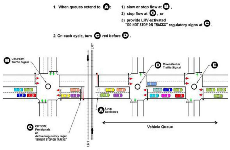
Source: Light Rail Service: Pedestrian and Vehicular Safety, Transit Cooperative Research Program Report 69.
The basic concept of queue prevention is as follows: If a queue is detected across a highway-rail crossing, traffic approaching the crossing will be stopped by a signal upstream of the crossing (signals B or C in Figure 44) to prevent the queue from building back across the tracks. As indicated, vehicle detectors can be installed at location A; if stopped or slow vehicles are detected at location A, logic built into the traffic control signal system could do the following:
- Stop the major flow of traffic at signal B (including control of turning traffic if necessary and appropriate)
- Stop the flow of traffic at signal C by using traffic signals on the near side of the crossing (such as pre-signals, previously described)
- Warn road users not to stop on the tracks by providing an activated, internally illuminated "DO NOT STOP ON TRACKS" sign (R8-8) mounted on a mast arm over each lane of traffic at location C (these signs would activate when queues are detected at location A)
- Provide exclusion zone cross-hatch striping, or other approved "Do Not Block" markings as described elsewhere in this Handbook
The advantage of queue management is that the crossing could potentially be kept clear of standing traffic regardless of whether a train was approaching the crossing, and the use of preemption would operate more as a fail-safe measure rather than a primary measure for keeping the tracks clear.
Management of Queueing at Frontage Roads
Use of STOP Signs
Frontage roads may present queueing challenges at crossings, especially if the CSD is very short and/or parallel roadway volumes are high. At locations where the frontage roadway is the minor street compared to the street with the crossing, it may be possible to install STOP signs on all approaches except the direction departing from the crossing. This treatment is illustrated in Figure 45. Note that STOP signs have been placed on both frontage road approaches to the crossing as well as the approach opposite the crossing. To advise road users that the traffic departing the crossing does not stop, supplemental plaques from the W4-4 series ("CROSS TRAFFIC DOES NOT STOP," "TRAFFIC FROM LEFT (RIGHT) DOES NOT STOP," or "ONCOMING TRAFFIC DOES NOT STOP") may be used in conjunction with the respective STOP signs.
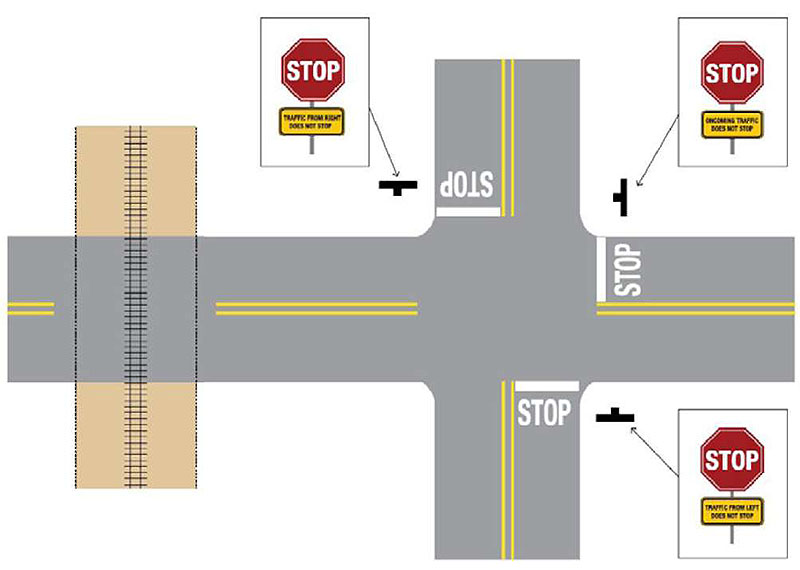
Source: Institute of Transportation Engineers.
Installation of New Traffic Control Signal
Where the parallel road is the major street at a frontage road intersection, use of STOP signs may be impractical. Such locations may justify the installation of a traffic control signal to ensure vehicles have an opportunity to clear the tracks prior to the arrival of a train. The MUTCD includes Warrant 9 (Section 4C.10) for a traffic control signal based on the proximity of an intersection to a crossing. The warrant is specifically intended to apply to situations in which the following occur:
- A major roadway runs more or less parallel to a line of railroad, and a minor roadway intersects both the major roadway and the line of railroad at grade.
- The resulting highway-highway intersection does not otherwise meet any of the other traffic control signal warrants in MUTCD.
- Motorist compliance with the existing (passive) traffic control devices at the highway-highway intersection often results in highway vehicles queuing across the nearby highway-railroad crossing.
- Other strategies to mitigate such queuing are deemed impractical, inappropriate, or not feasible.
It is likely that any traffic signals installed pursuant to this warrant would need to include provisions for railroad preemption which would in turn require modifications to track circuits to detect arriving trains. In addition, the proximity of the new signal would most likely require consideration for use of a pre-signal, queue cutter, or combination pre-signal/queue cutter.
Adjacent Railroad Crossings
Another circumstance which may result in queuing across a crossing is the presence of another nearby crossing–activation of the warning devices at one of the two crossings may result in queuing back across the adjacent crossing. In response to this concern, current practice (as presented in AREMA Chapter 3.1.11) may require interconnection between the two crossing warning systems.(29)
The recommended practice is dependent upon the distance between the two crossings:
- Adjacent crossings within 100 feet–the crossings should be treated as one individual crossing.
- Adjacent crossings with 100 to 200 feet of separation–Additional signs or other appropriate traffic control devices should be used to inform approaching road users of the long distance to cross the tracks. "Interior" active devices (such as flashing-light signals with or without crossing gates) may be omitted.
- Adjacent crossings over 200 feet apart–Where the distance between tracks exceeds 200 feet, the operation of the devices should provide for additional time for vehicles to clear the extended MTCD.
Additional guidance is in Part 3.1.11 of the AREMA Communications & Signals Manual.(29) Key provisions are as follows:
- Railroad companies should be provided with information regarding preemption and timing parameters to assist in their design of appropriate train detection circuitry. Unless the Diagnostic Team determines otherwise, normal sequence of traffic control signal indications should be preempted upon the approach of through trains to provide a preemption clearance interval of adequate duration to minimize the likelihood of vehicles not having sufficient time to clear the minimum track clearance distance prior to the arrival of the train. Flashing-light signal systems installed within 50 feet of any rail should be preempted upon the approach of a train.
- Activated by a supervised preemption interconnection, the approach of a train to a crossing should de-energize the interconnection or send a message via a fail-safe data communication protocol, which in turn should activate the traffic control signal controller preemption sequence. This should establish and maintain the preemption condition during the time the crossing warning system is activated to the point the automatic gates are energized to start their upward movement.
- At automatic gates, preemption clearance intervals which display green indications should be designed such that the green indications are not terminated until the automatic gates(s) is/are fully lowered.
Active Advance Warning Signs
The active advance warning sign (AAWS) consists of one or two 12-inch yellow warning beacons mounted in an assembly with the Advance Warning Sign (W10-1) and activated by detection of an approaching train. The beacons should be flashed in accordance with the provisions of MUTCD Chapter 4L. The AAWS is sometimes supplemented with a message, either active or passive, that indicates the meaning of the device, such as "TRAIN WHEN FLASHING." A passive supplemental message remains constant; an active supplemental message changes when the device is activated by the approach of a train. The AAWS should continue to be activated until the crossing signals have been deactivated.
A train-activated advance warning sign should be considered at locations where the crossing flashing-light signals cannot be seen until an approaching motorist has passed the decision point (the distance from the track from which a safe stop can be made). Use of the AAWS may require some modification of the track circuitry. Consideration should be given to providing a backup source of power in the event of commercial power failure. If such an advance device fails, the driver would not be alerted to the activated crossing controls. If there is concern for such failure, some agencies use a passive "RAILROAD SIGNAL AHEAD" sign to provide a full-time warning message.
The AAWS should be placed at the location where the advance warning sign would normally be placed, dependent on vehicle speed and the geometric conditions of the roadway. To enhance visibility at crossings with unusual geometry or site conditions, the devices may be cantilevered or installed on both sides of the highway. An engineering study should determine the most appropriate location.