Which Presentation Technique?
The guide covers a wide variety of techniques of varying complexity and levels of sophistication. As described above, the intended audience and the 'story' to be told will drive the decision on the best approach.
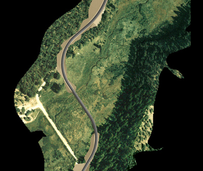
The two images below show what can be done with a simple surfaced road design model produced in Microstation. The road surface has been textured with a paving image, the cut slopes with a tan dirt texture, and an aerial has been draped over the surrounding terrain model. The first image is a plan view and would be best used to illustrate the layout of the road design, and the extent in coverage of the cut and fill slopes. It also illustrates the new alignments proximity to the existing dirt road and the creek bed.
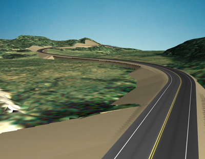
The second image from the same model is a camera based rendering from just above eye level. This image illustrates visibility of the cut slopes and the bridge from closer to a driver's perspective. The aerial is not as useful in this view, partially due to the low resolution of the image.
The following series of visualizations show a few different approaches used on the same project.
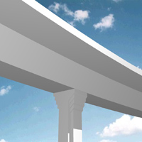
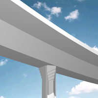
The design team was considering several alternatives for pier design. A number of the designs were quickly built up in 3D in Microstation to compare side by side. Only enough of the pier and overpass were modeled in order to see a bit of context. The views allowed the team to make some basic decisions on the desired design direction. Because they were mainly for the design team, the views didn't need to be highly detailed or polished. The renderings were output directly from Microstation at computer screen resolution.
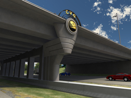
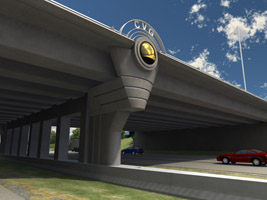
Two renderings of the pier with different color finishes
Once this pier and end cap design was refined enough, the decision was made to model and render at a high level of detail for presentation to the client. Since the pier and the end details were the main focus of the presentation, only the immediate surroundings were modeled, and no curvature of the deck was modeled. This simplified the modeling effort for the surrounding elements quite a bit. This view was rendered with 3D Studio max, but much of the section, elevation and detail line-work came from Microstation.
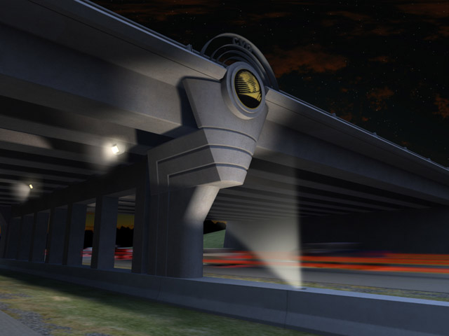
The high level of detailed also allowed for rendering with sophisticated and very realistic lighting.
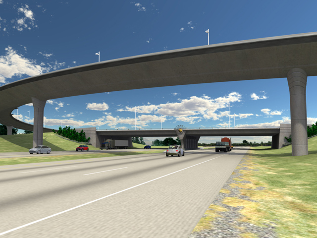
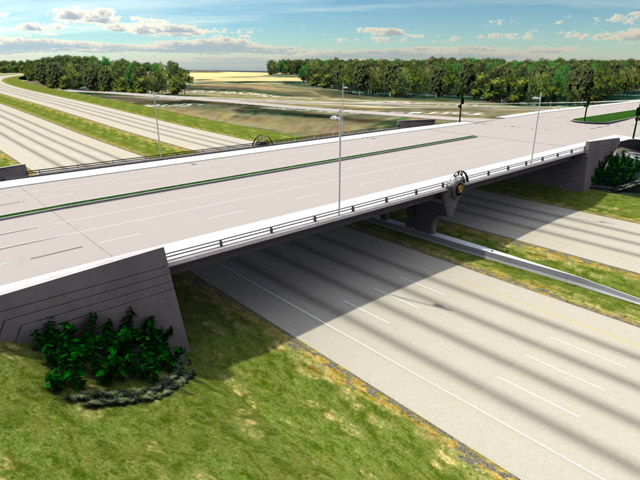
Once the design for the entire interchange complex was close to finished, it made sense to model everything in the area with a lot of detail, include striping, cars, landscaping, etc. This model could then be used to produce views from several angles, and to produce both driver's view and oblique animations. The views are being rendered in 3D Studio Max, but much of the base line-work, and some of the 3D elements were constructed by the design team in Microstation.
