Surfacing a Road Design
One of the most commonly used visualization techniques is to produce a TIN (triangulated irregular network) surface of the proposed roadway, shoulders, and the surrounding existing terrain. These surfaces are generated automatically from the section and plan information produced during the design process. The 3D model can then be used to produce rendered views and animations of the project from various viewpoint.
There are two toolsets for generating surfaces- the 3D Modeling Tools, and the DTM Tools. The 3D Modeling Tools will be the most commonly used technique, as they offer the most control over element creation and generate the best level of detail. The DTM tools are a little quicker and more useful for a 'quick and dirty' look at the design. The DTM tools are also useful for surfacing terrain around the design corridor. These tools are shown in Advanced 3D Objects.
Opening a 3D File
Before a surface can be generated from the design files, there are some basic prerequisites: the 2D design cross sections file, the plan view file that corresponds to section elements, a profile, and a blank 3D (seed) file that will contain the generated 3D sections and surfaces. The first step is to open a new 3D Microstation file. Open one of the standard FLH seed files (it must be a 3D file) to start, and attach the 2D project plan file as a reference. This file should include the plotted baseline for the project to be surfaced.
3D Modeling Tools - Produce a 3D Chain
Creation of the 3D surfaces is controlled from the 3D Modeling Tools dialog available through the Geopak menus:
APPLICATIONS>GEOPAK ROAD>3D Tools >3DModeling Tools
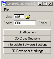
Input the job number and input or select the chain name. It is a good idea to set 3D model preferences before generating surfaces, as these will control the density of triangles generated and the accuracy of the section lines required. The dialog is accessed from the File pulldown on the 3D Modeling Tools dialog
File>Preferences
Tolerance defines the minimum distance resolved by Geopak between two endpoints or elements in the 2D drawings- if two endpoints don't quite connect, they will be assumed to be connected if they are within this distance. Playing with different tolerances can help correct for some problems within the sections.
Minimum Rule Spacing determines the number of segments B-spline surfaces will be subdivided by, and ultimately the number of polygons that will be generated between each of the 3D sections along the chain. This value sets the maximum size of a subdivision, for curved sections of roadway, the number will need to be smaller than for straight sections. In the following examples, the sections are 20M apart. The first set of surfaces were generated with a Rule Spacing of 4, the second with a Rule spacing of 10.
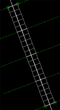
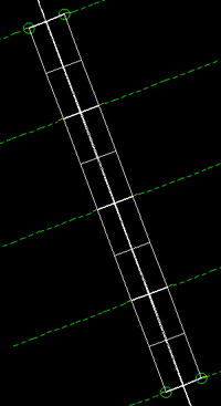
Create the 3D Chainfile from Plan and Profile Information
Open the 3D alignments dialog:
3D Modeling Tools>3D Alignments
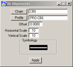
Select the Profile by name, and set the horizontal and vertical scale. As long as these are equal, the 3D chain will be drawn in true X,Y and Z. If they are distorted, the elevations of the chain will be distorted. Set the desired level, color and linestyles for the 3D chain by clicking on the Symbology button.
3D centerlines are also useful for models being built in other rendering applications such as 3D Studio Max, the surfaces can be 'lofted' using sections swept along the 3D centerline.
3D Modeling Tools - 3D Cross Sections
This step will convert the 2D sections into 3D sections along the 3D alignment chain. Open the 3D Cross Sections dialog:
3D Modeling Tools>3D Cross Sections
Specify the Cross Section File, and set station limits for the run. Geopak will only generate sections between the designated station inputs. It is better to produce the 3D sections in smaller groups and correct problems as they occur.
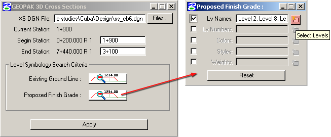
Select section elements to be converted by indicating specific symbology with the buttons in Search Criteria- i.e. level, color, lineweight, style. Multiple entries can be comma delineated, or just selected using the Select Levels button to the right of the Search Criteria dialog. Be careful to include all needed levels- only the section elements with symbology selected for both existing and proposed will be used to generate the 3D sections. If key section elements are not included in the symbology list, the 3D sections may not be created correctly. Hit Apply, and the tool will create 3D versions of each cross section at the proper station along the 3D chain.
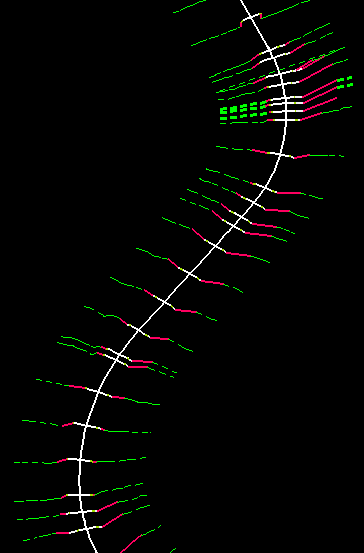
Successful 3D sections should look like this.
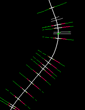
Broken section such as these will not surface correctly
Troubleshooting the Cross Sections
Two common problems with generating 3D sections are symbology selection (not being specific enough with colors or levels) and section element lines not meeting at joints. If there are small gaps between section line joints, the surfaces will not be generated properly. The fixes are to either adjust the tolerance up or down, or check the sections and snap or trim the section line ends where they don't connect. Sometimes eliminating colors from the symbology list for conflicting elements can correct some problems, but only for colors that are not used on significant elements. Check the color and level definitions in the section file to look for conflicts.
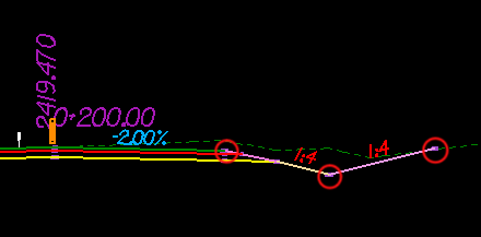
Typical locations where segments may not join correctly
3D Modeling Tools - Interpolate Surfaces between 3D Sections
This step is the trickiest and most prone to problems. It is advisable to move through the alignment in small segments, surfacing (and debugging..) each in turn. Sometimes the 3D sections must be debugged and regenerated in order to get the surfaces to work. Open the dialog from 3D Modeling Tools:
3D Modeling Tools>Interpolate Between Sections
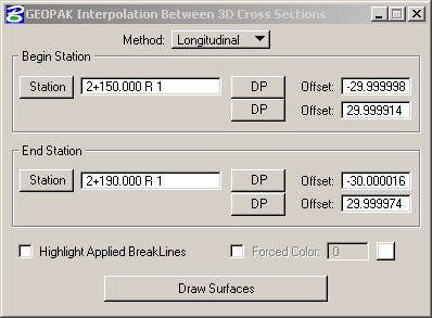
The method used will most likely be Longitudinal, (for a 2D horizontal alignment). If the horizontal alignment file is 3D, select Surfaces.
Select a range of 3D sections to be surfaced. It is advisable to work in short sections and check the results. Offsets will be chosen automatically if a station number is input. It is easier to graphically select stations and offsets in the plan view: Click a station button in the dialog then select a section in the view and the appropriate station location will be filled in with the outermost Offsets filled in; or just press the top DP button under Begin Station, then snap to a point in the model on the section at the beginning station to the left of the centerline at the desired offset distance. Repeat this for the right side: press DP, then select a point in plan at the desired offset distance to the right of the centerline. This process is repeated for the End Station: pressing DP buttons and selecting point on the end section in the plan view.
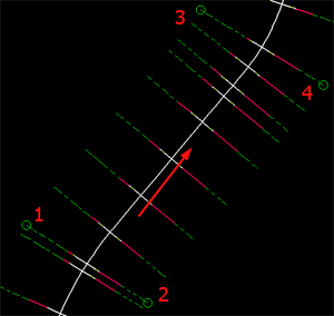
The circles show where and in what order DP offsets have been snapped to on 3D sections, arrow is direction of stations.
Press Draw Surfaces and wait for the result.
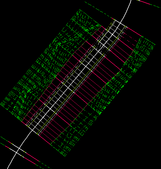
This is the point where problems with the sections may surface- line segments that don't meet, level inconsistencies, etc. Note the "hole" in the upper left segment of the surface in the above image. Individual surface segments can be built by snapping to section segments on either side:
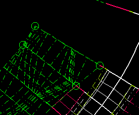
Proceed slowly along the roadway, filling in holes where they do not generate with larger selections. An alternative is to try to correct the problem in the 2D section and redraw the offending 3D section. Where section information 'transitions', i.e. road widening, ends of cut slopes, etc., there will always be difficulties in the surfaces lining up. Sometimes individual faces may need to be built by snapping to certain vertices on the segments. If this doesn't work, surfaces can be built using the Microstation surfacing tools.
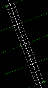
Snapping to individual segments of the 3D sections will generate surfaces for just those section elements. In this example, only the roadway surface is being created by snapping to the ends of the segment representing the paved surface in the 3D section:
3D Modeling Tools - Pavement Markings
The Pavement Markings Tool with Geopak 3D Modeling Tools is a bit tricky and does not always produce reliable results. Success will depend on the vertical curvature in the roadway, and the separation between the road and striping surface objects. Another method for placing stripes is the use of a texture mapped material. This is described in Advanced Materials and Lighting.
