Cuba La Cueva - 3D Modeling
The Cuba La Cueva project was a pair of photosims showing a re-alignment and a proposed bridge in a scenic valley in New Mexico. This is a classic photosimulation example. A 3D model of the road design and bridge were produced in Microstation, as well as the surrounding context as a 3D DTM. A camera match was done in 3D Studio Max over a high resolution background image. The bridge and road surface were rendered in 3D Studio, composited into the background and touched up in Photoshop. The cars, people and added landscaping were painted in in Photoshop.
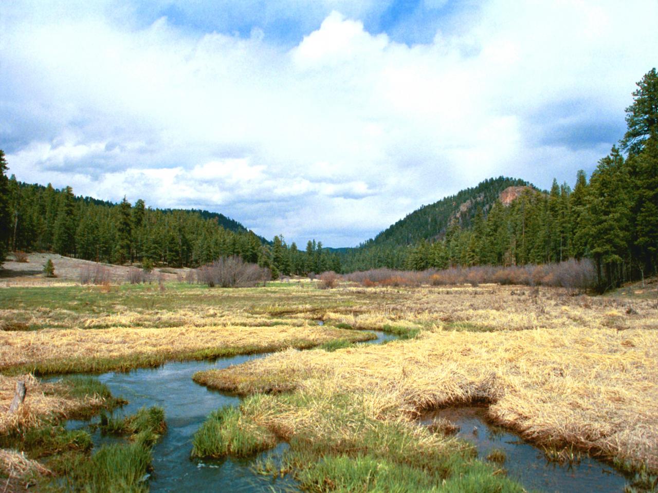
Cuba La Cueva 1 Existing (click image for high resolution view - 1.6MB)
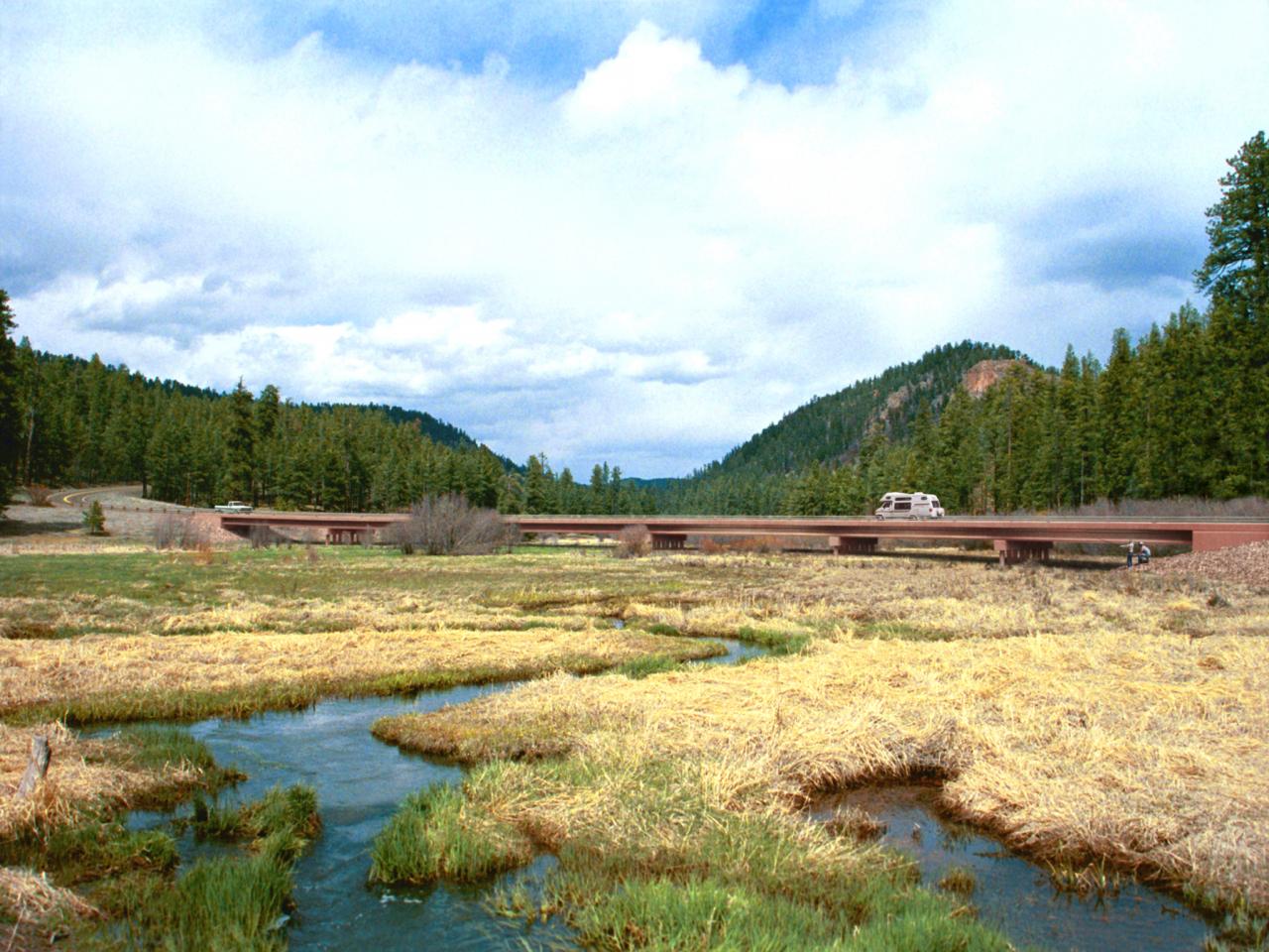
Cuba La Cueva 1 Proposed (click image for high resolution view - 1.6MB)
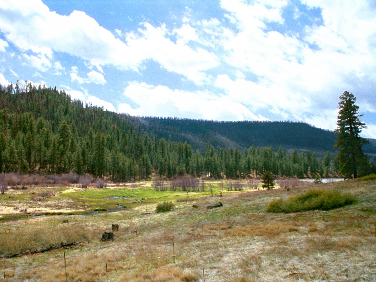
Cuba La Cueva 2 Existing (click image for high resolution view - 1.4MB)
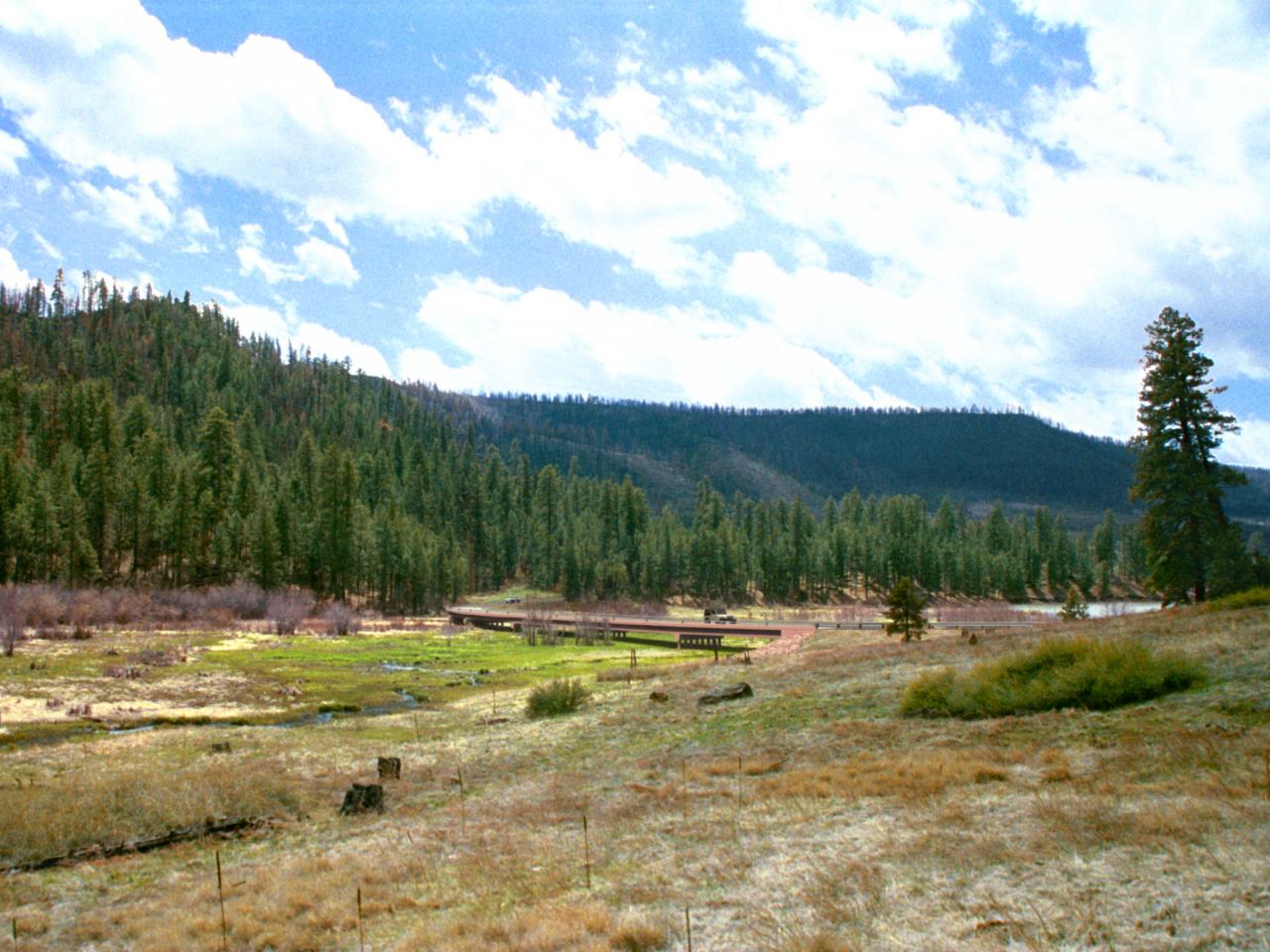
Cuba La Cueva 2 Proposed (click image for high resolution view - 1.4MB)
The Modeling and Rendering Process
A preferred alternative for the road design was developed in Geopak, and the first steps were to produce a 3D Model surface of the road alignment, and a DTM of the surrounding terrain covered by the survey data in Microstation. The existing road can be seen in the lower portion of the DTM (green surface). Knowing where this road was in the model and in the background photos helped in the camera matching process.
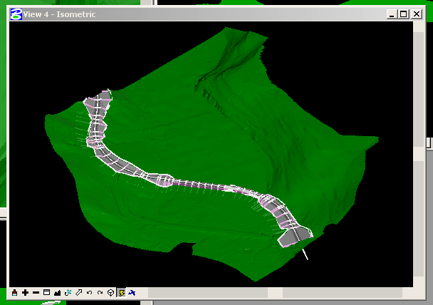
This model was exported as a DXF file and imported into 3D Studio Max. (The preferred method in V8 would be to 'Save As' a DWG file which can then be opened directly in 3DS Max. 3D Rendering Applications discusses some issues with exporting Microstation data to 3D rendering applications.
The camera matches to the background photos for this project were done in 3DS Max, which allow the user to interactively move the camera and camera target while displaying the 3D model over the background. The process is the same as the matching process described for Microstation in Advanced Paint Techniques. The surfaces in 3DS Max can be rendered in the viewport as wireframe or shaded, just as in Microstation. A lower resolution 'proxy' image, at the same aspect ratio as the original, is created for the camera match so that the load times into 3DS Max are quicker. The rendering is done at the higher resolution to match the original background.
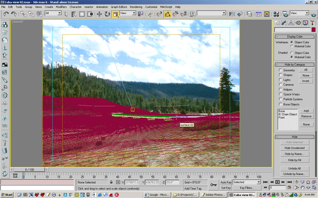
The magenta surface is the area DTM being matched visually to the photo
Once the camera match is sufficient, materials are added to the bridge model and visible road surfaces. This model consisted primarily of concrete and metal textures for the bridge, and a road surface map that included the asphalt and striping.
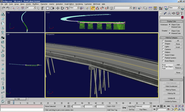

Concrete Texture Map
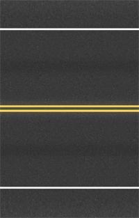
Road Surface Texture Map
A light source is set up for the model that matches the lighting in the photo. For these views, the light was set up high and a little to the left and away from the camera. The lighting in the photos is very flat and diffuse, so a direct light with very soft shadows, and a skylight which also adds very soft shadows, were used. The more closely the lighting matches the photo, the more realistic the rendering of the model will be when composited. Some adjustment of color and contrast can be made in the paint program, but the best results are obtained with a good rendering.
The Photoshop Image
Smart setup of the paint file is an essential step in the photosim process. Use of layers, and good naming conventions allow for easier changes and updates to the image. The rendered layers, in this case the bridge and road surface, are always left on a separate layer, and details and foreground elements are on separate layers as well.
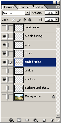
In the layer list above and in the image below, the bridge, scene details, and the bridge shadow are on separate layer and set to visible. The color, contrast, positioning, and visibility of each layer can be controlled separately. In most 3D rendering applications, the shadows can be rendered separately onto an 'invisible' surface, and placed on their own layer in the paint file. The shadow can then be adjusted separately for the best effect.
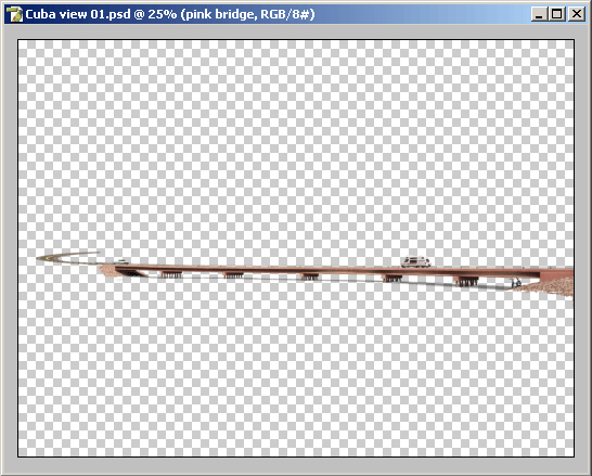
In the image below, the foreground elements, also on separate layers, have been set to visible.
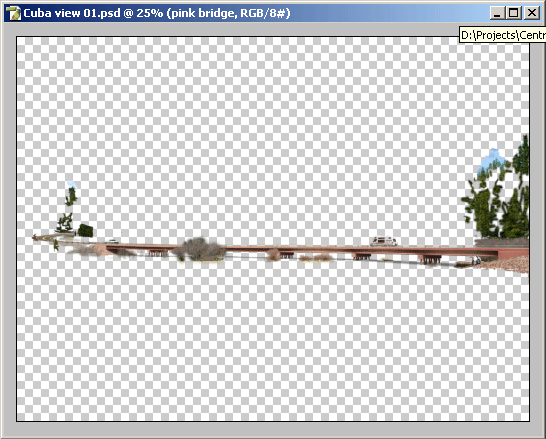
With the bridge being on a separate layer, it was very easy during the process to alter the color of the concrete from gray to pink in Photoshop, without needing to re-render.
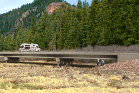
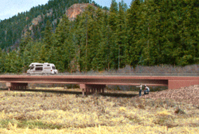
Here is the final photosim again- click the image below for high resolution (1.6MB):

