Creating & Rendering Camera Views
The best way to produce perspective renderings of the 3D model from specific viewpoints is to set up a camera in the scene. Using a camera view is the only way to create a view from a specific X,Y,Z location within the model. A camera view can be set up either by navigating interactively in a viewport in a 3D file (essentially moving and rotating the camera around) until the desired view is found, or by explicitly specifying a view position and direction, or 'target'. The camera position and target can be 'snapped' to the surface of the model and moved up to view height. The target is a second X,Y,Z, point that is used to direct the camera- it is the center of the camera "viewfinder". The camera view axis is the line between the two points. The camera view also has a view angle, or "field-of-view". Changing this angle is the equivalent of zooming a camera in or out.
Creating Camera Views
Camera views are created in a number of ways, the easiest is to convert an existing view through the Settings pulldown menu:
SETTINGS>CAMERA>ON
and click into a viewport. That viewport will switch to a camera view, and the camera position can be manipulated by clicking on the Navigate Camera button on the View Control Toolbar at the bottom of the viewport:

this will bring up the Navigate Camera dialog:
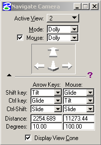
There are several different mouse and key control modes for interactively navigating with the camera. These movements take a little getting used to, especially in a large model. The Navigate Camera controls are designed to be used with or without a camera turned on in the scene.
Define Camera Tool
A more robust tool for camera manipulation is available through the Rendering Tools palette:
TOOLS>VISUALIZATION>RENDERING

The button brings up this dialog:
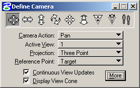
The buttons along the top define Camera Action which is also the top pulldown. There are pans which move the camera or target left/right up/down, rotation, and dolly movements which move the camera in and out.
The Projection type is important, a photograph is a three-point perspective, this will be needed for a camera match. The two-point perspective mode will keep verticals parallel in a rendering which is useful for images of structures or architectural elements.
The Reference Point setting defines whether movement occurs around the target (camera moves) or eye (target moves)
Push the More button to expand the Dialog:
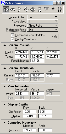
Using these expanded dialogs allow setting of specific camera parameters. If, for instance, a camera position is known, the X, Y and Z values can be inserted here. The field of view or camera orientation can be defined here as well. These settings are useful as starting points for a camera matching process. The best information for position can be defined, then the camera tweaked to match a photo.
View Cone Manipulation of Cameras
Once a camera has been defined for a viewport, and the Display View Cone option is checked, a schematic representation of the camera is drawn in the non-active (non-camera) viewports:
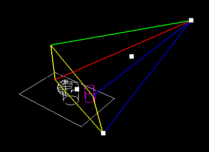
The camera position and target can be moved by dragging the correct targets on the view cone. Field-of-view can be manipulated as well. It is difficult to make small adjustments to the settings in this mode, the Define Camera dialog is better for that.
Creating Cameras at Specific Locations
There are several methods for specifying camera and target locations, (in addition to defining X,Y, Z positions). One of the most precise is to create construction lines that can be snapped to, or snapping to the surface of the model and then moving up to viewer height. The ends of the lines represent the location (X,Y, and Z) of the camera and the target. Another method is to set the active depth of a top view to the desired camera elevation, or Z, and place the camera based on plan view information.
The camera can be created with the Camera Set-Up dialog under Settings:
SETTINGS>CAMERA>SET-UP
The dialog comes up after a viewport is selected as the camera view:
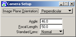
before placing the camera in a viewport, the field of view can be set as either an angle, a focal length (based on 35mm camera) or a set of standard lens types- wide, normal, telephoto, etc. The camera can then be created in any viewport, using snaps, or placing it in plan. The fist click is the target, or view direction. The second click is the camera location.
Once the camera has been created, use the Define Camera tools to tweak the camera location and target to get the perspective in the view to where you want it. Several different camera views can be saved using the Saved Views Utility described in section 2.1. The different views can then be recalled to any viewport later.
Rendering the View
There are several levels of rendering modes, or view display modes, available in Microstation. The most common are wireframe or wiremesh. Other modes such as smooth, phong, or ray-traced, produce higher quality images, but at longer render times depending on model size. In order to use texture maps, lighting, and shadows, higher end rendering modes are required. The basic render modes are available from the Change View Display Mode on the View Controls for the viewport:

The list of modes available:
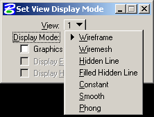
Saving Rendered Views
There are few ways to create images from rendered views. The method with the most control is the Save Image Utility, found under the Utilities Menu:
UTILITIES>IMAGE>SAVE...
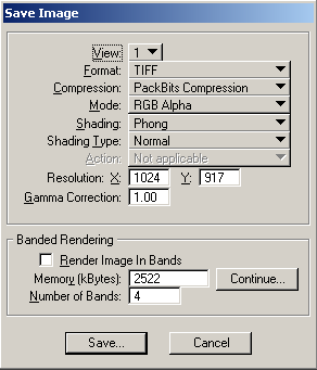
There are a wide variety of image types available from the Save Image utility:
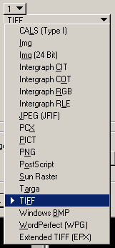
The dialog also allows you to specify image compression, the shading type and the resolution of the rendered image.
