Bautista Canyon - Modeling
The Bautista Canyon photosims are a good example of photosimulations produced with Microstation and a paint application. A 3D model of the road design was produced in Microstation, as well as the surrounding context as a 3D DTM. the road surface was texture mapped with an image of asphalt and striping. A camera was placed in the scene at the location from which the background image was taken. A wireframe view of the model was 'printed' using one of the image based print drivers, and superimposed over the background image. The wireframe was then scaled and moved until it lined up with the existing condition photo. The wireframe layer was then used as a 'template' to paint in the proposed road and embankments.
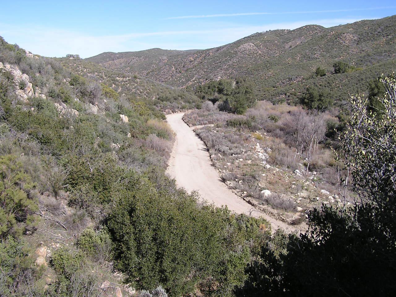
Bautista Canyon Road 1 Existing (click image for high resolution view - 2.1MB)
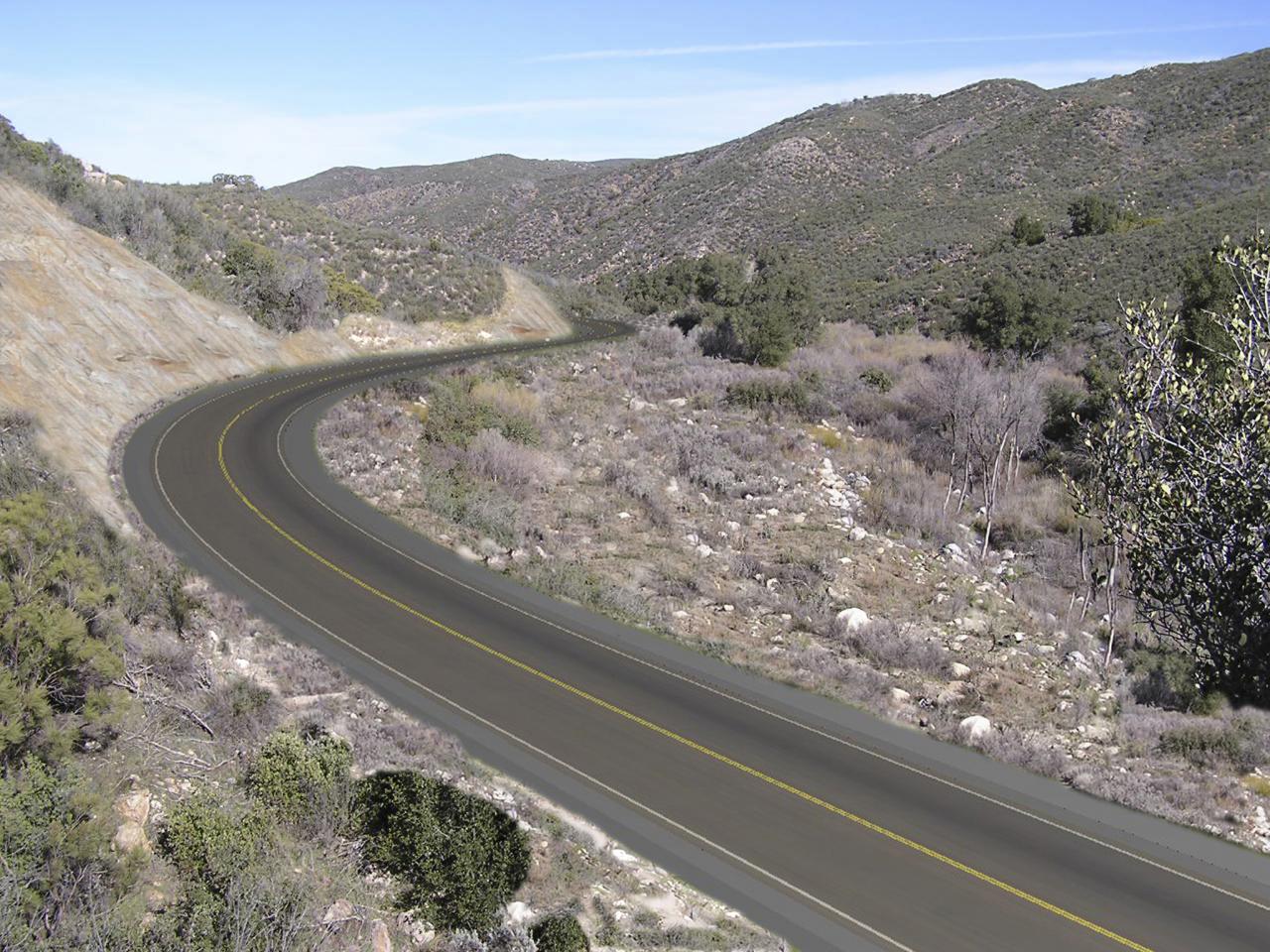
Bautista Canyon Road 1 Proposed (click image for high resolution view - 1.3MB)
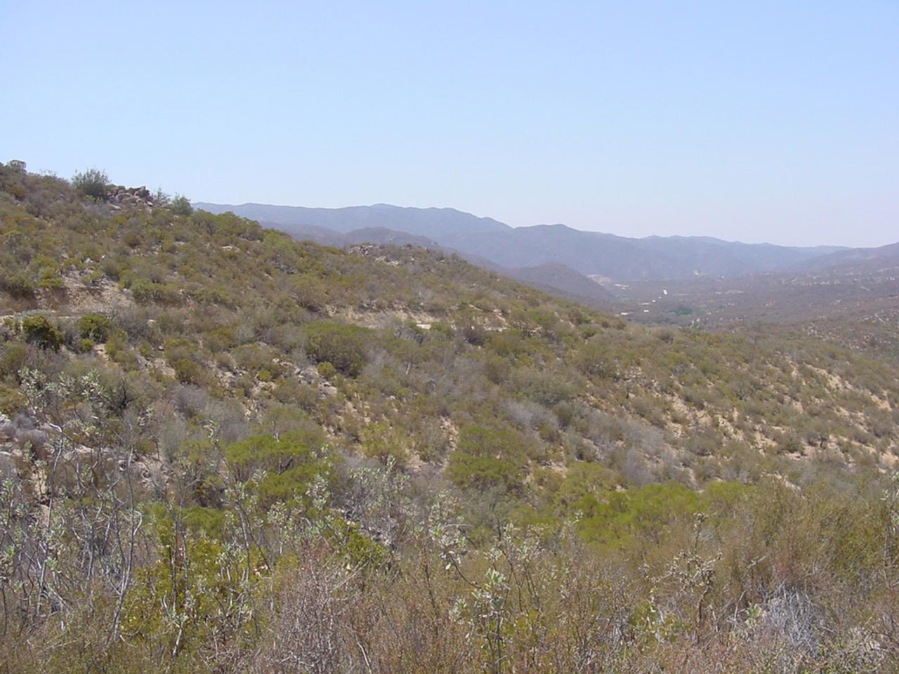
Bautista Canyon Road 2 Existing (click image for high resolution view - 1MB)
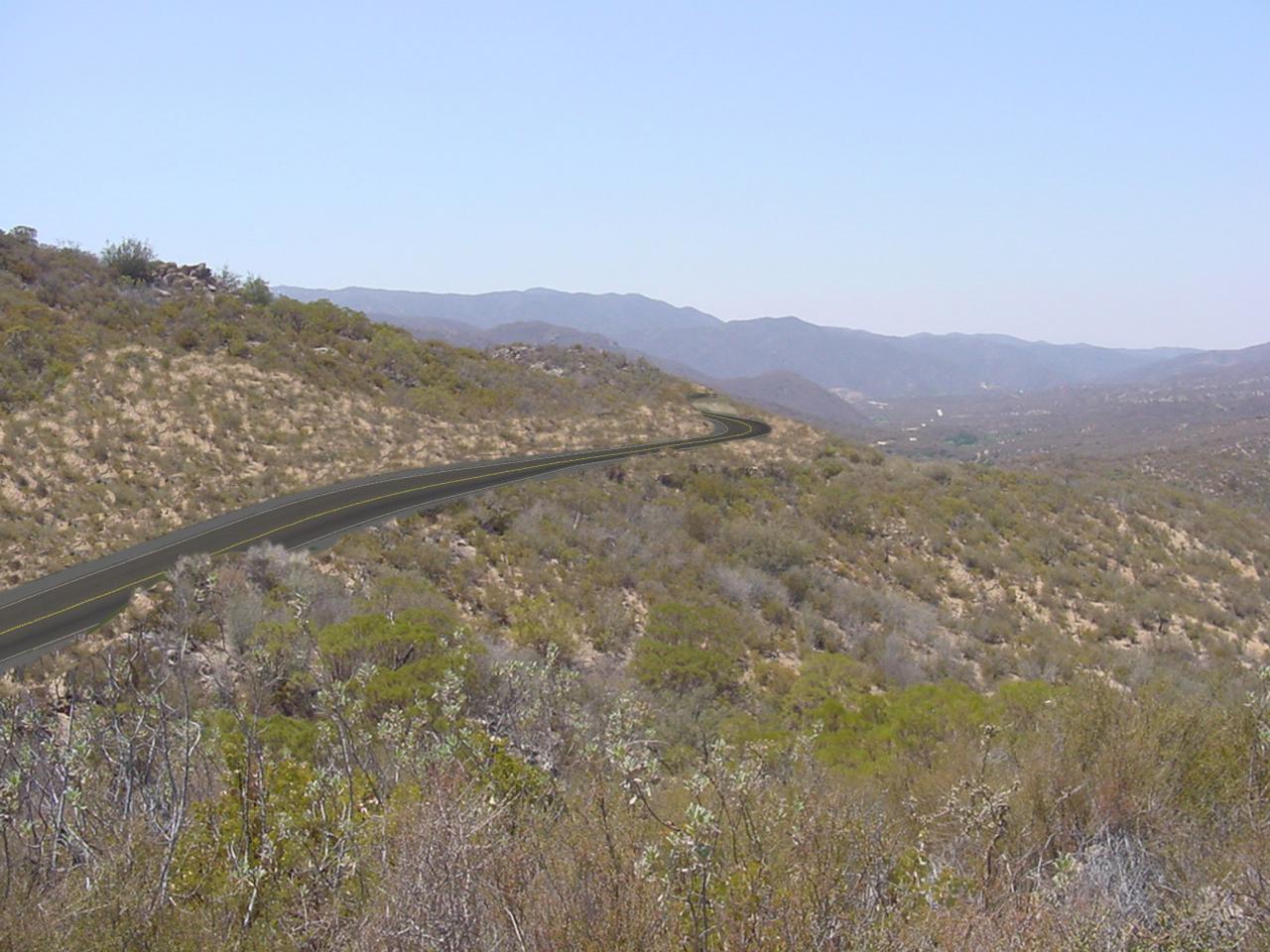
Bautista Canyon Road 2 Proposed (click image for high resolution view - 1.6MB)
Microstation Setup
A preferred alternative for the road design was developed by FLHD in Geopak, and the first steps were to produce a 3D Model surface of the road alignment, and a DTM of the surrounding terrain covered by the survey data in Microstation. The surfacing process is discussed in Creating Surfaces from Road Design.
Documentation of the location where the photos were taken allowed the creation of virtual cameras in Microstation at the same locations in the project site. Good documentation at the time the photos are taken- noting existing features in the site data, using a high resolution aerial for reference, placing targets, or even capturing GPS locations, can make the camera placement in the 3D model much easier.
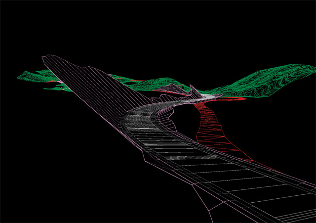
Wireframe view of road surface model
The target for the camera is placed in the 3D model so that the center of the viewport matches the center of the background photo as closely as can be determined. If the virtual camera location matches the real camera location on-site, and the target is placed at the center of the background view, the perspective of the camera view in Microstation will match the perspective of the photo. The field of view then needs to be the same or greater than the photo, and the wireframe output from the viewport can be scaled and matched to the photo in Photoshop.
The process for camera matching in Microstation is described in Advanced Paint Techniques.
The road surface can be rendered in Microstation with the asphalt texture and the striping in place by applying a material with a texture map, or Pattern Map material applied to the road surface element. The road texture map is repeated along the surfaced road geometry, and rendered in perspective to match the background view. The Pattern Map material application process is shown in Advanced Materials and Lighting, the Image Save utility is outlined in Creating and Rendering Camera Views.
Painting the Image
With the image from Microstation overlayed correctly on the photo, the road surfaces and cut/fill slopes will be shown in the right locations and perspective. The cut slopes can then be painted in using textures the match the background photo. Using elements of the background photo, the existing road is then painted out.
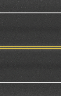
Road Surface Texture Map
Cut Slope Surface Texture
Here is the final photosim again- click the image for high resolution (1.3MB):

