Advanced Materials & Lighting
Simple materials and lighting definitions were discussed in Basic Materials and Lighting. This section will cover the use of texture maps with materials and more sophisticated lighting.
Using more advanced materials and shaders
The Materials Editor Dialog can be accessed through the Settings pulldown, or on the Rendering Toolbar:

By selecting Advanced Mode, Samples, and Descriptions under the View Menu, more materials settings are made available:
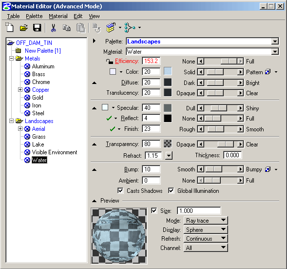
The first panel, the Diffuse properties control base color, brightness and translucency. The button on the right opens the pattern dialog which controls diffuse texture maps. The second panel contains the Specular properties- shininess and reflectivity. The third panel controls Transparency, the last has bump and ambient settings and a button for bump map setup.
Adding Texture Maps to Surfaces
The best way to get realistic finishes on objects in a scene is with texture maps as part of the materials definitions. The texture map can be scaled and placed onto objects in several ways, and the map can be blended with the other settings for the material. Mapping is defined with the Pattern dialog accessed with the button to the right of the Diffuse properties (for the Pattern map) on the Materials Dialog.
The following dialog shows a new palette named 'Cuba LaCueva', defined using PALETTE>NEW, and three new materials under that palette, MATERIAL>NEW. When Materials definition is finished, the Table can be saved with all defined Palettes and Materials: TABLE>SAVE AS...
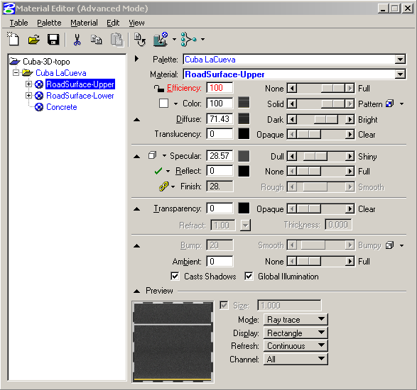
Each of the materials has a texture map assigned as a Pattern map. These are assigned using the Pattern dialog accessed from the button to the right of the Diffuse properties. Two materials have been defined for a road surface: RoadSurface-Upper and RoadSurface-Lower, for the two halves of the road 3D surface. They ended up as different elements during the surfacing process as they were defined by separate segments in the section files.
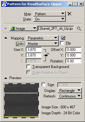
An image is selected with the 'Looking Glass' icon and the image can be scaled, moved and rotated relative to geometry or the scene using the Mapping setup properties. A preview of the resulting mapping is shown at the bottom. The typical Mapping would be Parametric in Surface or Master Units. Master allows scaling in real world coordinates if the true dimension of the area covered by the map is known. In the definition above, the road surface texture is defined as 3.87 meters square- based on the width in meters of one half of the road alignment. The mapping for the surface follows the centerline of the road, so the map is scaled correctly along the alignment. The Material is Attached to Element by selecting elements along each half of the road.
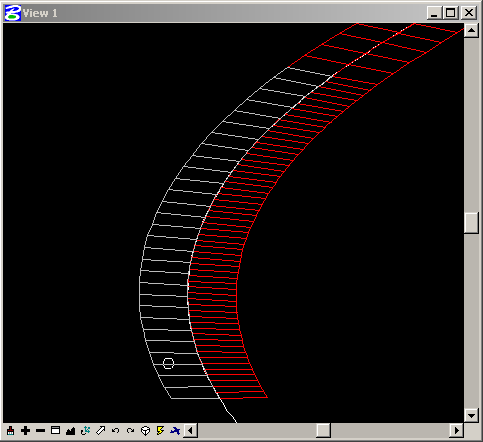
Element on Left Half is Selected
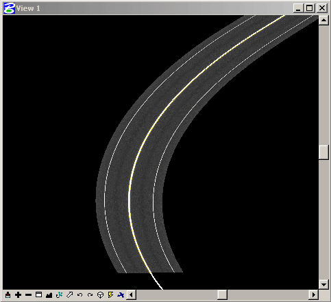
The Textured Road Surface
Elevation Drape with an Aerial Image
If the model includes geo-referenced aerial images already aligned in plan, the process of 'draping' these images is straightforward. With Microstation V8 the image alignment information will be accessible through the Raster Manager: FILE>RASTER MANAGER. The same information should be available from Descartes if that was the image source. Double click on the image listed in Raster Manager and select the Location Tab at the top of the Attachment Settings dialog. Note the Origin and Dimensions settings:
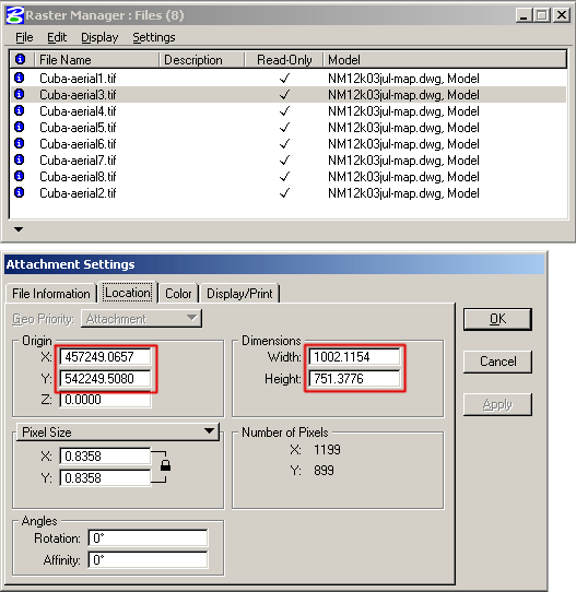
Create a new patterned material for the aerial drape. Set the material Pattern mapping to Elevation Drape, and use the above settings for image offset and image size (respectively) in the Pattern settings dialog as shown below. Then attach this material to the level containing the surface to be 'draped' with the aerial texture.
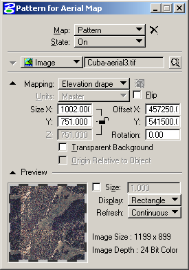
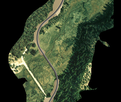
3D Terrain Model with Aerial Draped Texture Map
Blending Textures with Color
Not all texture maps are designed to 'tile' properly, and the edges between repeated copies of the image can be detrimental to the success of the material. Some texture maps are just too saturated, or need some slight color correction. By blending the texture map with the base color, the intensity of the texture map is reduced, and more of the base color comes through.
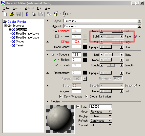
The slider for color is set at 35, meaning the material will be a blend of 35% texture map and 65% color as defined in the box to the left of the slider. For concrete, which is relatively dull, a lower setting for specularity is better. In this material it has been set at 12.3. Roughness also effects the highlight, this material has been set to slightly more rough than smooth (39).
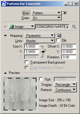
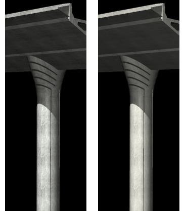
The texture map for the concrete material has been scaled literally to 5x5 master units. The image below shows the difference between the texture at 100% on the left, and at 35% on the right.
Setting up Lights for Better Rendering
Custom lights can be defined and modified with the Define Light dialog accessed from SETTINGS>RENDERING>SOURCE LIGHTING or from the Render Toolbar:

The following dialog comes up, Under Mode, set to Create to insert a new light, Type is set to the kind of light desired. The dialog shows a newly created Spot Light. The settings can be changed before creating a light.Once Create is selected, data point for the light position, then data point again for the light target. The easiest way to define the light position is with a construction line to snap to, the target can be snapped to an object in the scene. In order to see the light object in the viewport, Constructions must be set on in the View Attributes.
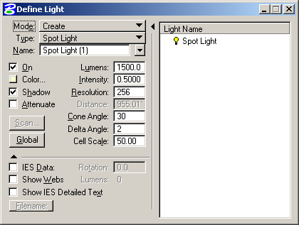
The settings for the light can be defined before creation, or by setting Mode to Modify and Method to Edit Light and select the light to be set up.

Light intensity is a combination of Lumens value and intensity setting, but for most cases adjusting Intensitywill be sufficient. If shadows are on, the other critical setting for non-raytraced lights is the Resolution. This sets the quality of the shadow map calculated for the rendering. Larger scenes with larger areas of coverage will need higher resolution maps, and longer render times. The map size will affect the shadow crispness as can be seen in the following renders:
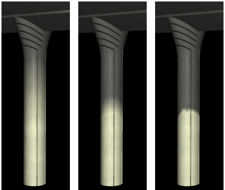
The render on the left used a map size of 256 (default), the middle 1024, and the right 4096.
The ambient light, or the brightness of the shadows, is controlled by the Global Light Settings for Ambient and Flashbulb. The dialog can be reached from the Global button on the Define Light dialog.
Solar Lighting System
A very easy way to set up lighting is to use the Solar light source. The tool is also useful if an evaluation of potential shadows from a project need to be evaluated. The Solar Light setup is on the Global Lighting dialog: SETTING>RENDERING>GLOBAL LIGHTING or from the Rendering Toolbar:

A light source is created by defining a Location- either by city name or by longitude/latitude. Then Time is set: a date and time of day is set and the light source is created at the proper location. The parameters for date and time can then be changed for successive renders.
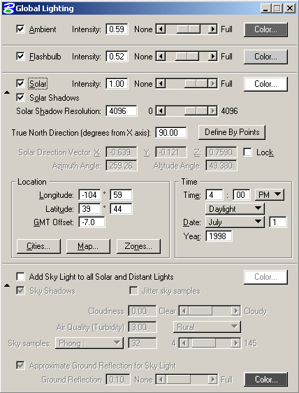
If Shadows are set, the resolution must be set at a resolution that will give the desired shadow effect. See the description for resolution above. This tool is a quick way to set up a light, and by altering date and time, adjusting the light for the desired render quality.
