Advanced 3D Objects
Microstation and Geopak include several 3D modeling, surfacing, and modification tools. There are often several ways to construct a similar 3D object. A few of the basic objects and techniques are covered in this section.
3D Primitives and 3D Construction Tools
Most simple 3D objects will begin as 3D primitives or constructed elements. These two toolbars are available from the Tools Menu
TOOLS>3D MAIN>3D PRIMITIVES or CONSTRUCT
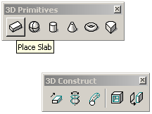
The 3D primitives toolbar has buttons for creating basic shapes like boxes (slab), cylinders and spheres. The objects are defined by setting size parameters and placing the object, or by dragging the sizes for those parameters in different viewports. A slab length and width could be drawn in plan, and the height set in a front view. The rotation for the base of the object can be set interactively as well. Parameters for a cylinder would be diameter of the base and height
The 3D Construct tools are used to generate 3D objects from 2D elements. the most commonly used tool is Extrude, a 2D shape is extruded to a defined height. A complex column shape could be drawn in plan, then extruded into a solid of the desired height. Another useful 3D Construct tool is the Extrude Along Path tool. The 2D shape can be extruded along a complex 3D line. This tool can be used for extruding road or deck shapes along a 3D centerline in a design file.
Boolean Operations
The 3D Modify toolbar includes the boolean tools:
TOOLS>3D MAIN>3D MODIFY

These tools, Construct Union, Construct Intersection, and Construct Difference are used to create new objects by mixing other objects. The union melds two objects together, subtract cuts one object out of another, and intersection calculates the shared volume of the two objects. Microstation creates clean geometry out of the results.
Surfacing Tools
More complex objects and surfaces can be constructed using the Surface Modeling Tools.
TOOLS>SURFACE MODELING >CREATE SURFACES

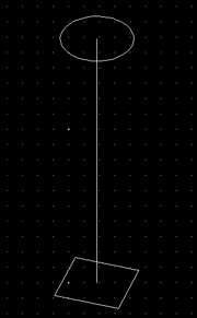
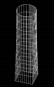
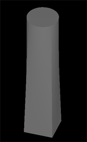
Another useful Surface Tool is the Construct by Section or Network. The tool build surfaces between two segments. This tool could be used to fill in stubborn sections of a roadway model that can not be made to work with the Geopak 3D Modeling tools.

Below is an example of surfaces being built between two 3D sections constructed with Geopak. Snapping to the endpoints of the sections defines the new surface.
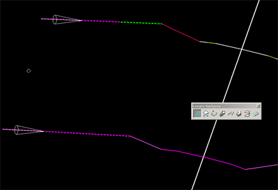
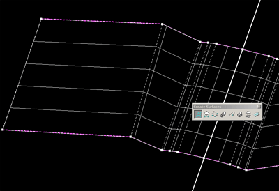
The segmentation of the various surface tools is controlled by the B-Spline and 3D Dialog under the Element menu: ELEMENT>B-SPLINE AND 3D
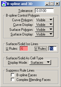
The Surface/Solid Iso Lines parameters control the number of surface subdivisions. In the sample above the U Rule setting was 6, resulting in 6 line segments, and 5 surface sections between the two defining 3D sections.
Geopak Digital Terrain Modeling Tools
The DTM Tools are used for creating and modifying surfaces from 3D point data. Some examples of source data are: the existing site survey point data, 3D data extracted from a DGN file, or 3D data generated by GeoPak from a roadway design file. Surfaces can be produced as TIN's (Triangulated Irregular Networks) or lattices- a mesh based on a grid cell of uniform size, for instance 1Mx1M squares. These surfaces can be created within or outside of specified polygonal boundaries. One common use for the tool is to create an existing context surface surrounding the proposed road design 3D model. The surface would be built around the bounding polyline, or limit of work area, for the 3D road model, and because the same existing data is used in generating the edge surfaces of the road design DTM, the two surfaces should line up seamlessly.
Surfacing the 3D TIN
Most roadway design projects begin with either a .TIN or .DAT file generated from survey data for the project. This data can easily be turned into a viewable surface using Geopak DTM tools. If the data is a .DAT file, it will need to be converted to a TIN using the Build Triangles Tool:
APPLICATIONS>GEOPAK ROAD>DTM TOOLS, select the Build Triangles button
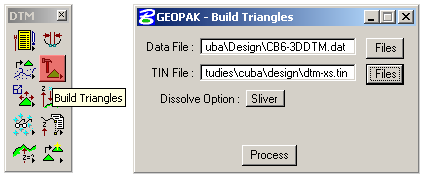
select the 3D Data file, and then define a new TIN file. The Dissolve Option and Side Length control the creation of long slivered triangles at the edges of the TIN. The Sliver Option is automatic and will do a decent job on an overall terrain model. The Side option is the most useful with roadway surfaces, and is described later. Hit Process to create the TIN file.
Load the DTM Features
Any TIN, DAT, or Lattice file can be loaded and converted to a DGN 3D surface using the Load DTM Tool on the same DTM Tool palette. APPLICATIONS>GEOPAK ROAD>DTM TOOLS, select the Load DTM Featuresbutton.
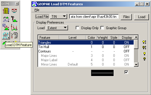
Select the TIN file type and choose the file, then turn on display for the desired features. The Triangles feature is the surface itself, the Tin Hull is the bounding polygon. Contours can be extracted as a feature from the TIN as well. Set the level and color for the features by selecting the feature and double clicking the symbology setup at the bottom of the dialog. Checking Display Only will display the surface without generating geometry, and is useful while experimenting with different setups. Hit the Load button and the surfaces (and Hull) will be drawn on the defined levels. The surface can now be saved as a DGN 3D file.
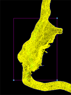
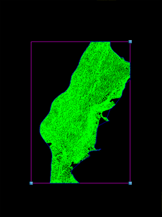
Loading the Extent of the TIN loads everything in the file. By setting the Load option to Fence, and selection a region within the overall TIN, a smaller, more manageable surface can be produced. Using the Display Only option, find the area of the TIN that is needed, draw a Selection Fence around it, then set the Load option to For Fence.

The TIN below was created using a rectangular fence area. On the left the fence is drawn over the displayed TIN, on the right is the resulting cropped surface.
3D Data File from Road Design File
Geopak includes a tool to build a DTM surface directly from a design file. Geopak does this automatically using the 2D cross sections file and the Cross Section Reports Tool:
APPLICATIONS>GEOPAK ROAD>CROSS SECTION>REPORTS

Select DTM Prop 3D for the following dialog:
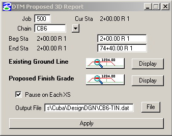
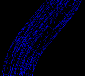
In essence, this tool creates a 3D data file from 3D sections similar to what would be generated using the 3D Modeling tools. No interpolation is done between sections. If the section interval is small enough, this tool can be useful (and much simpler than the 3D Modeling tools).The dialog is similar to the 3D Modeling tools setup: select a chain, beginning and ending stations, then select the proper symbology from the cross section files for existing and proposed sections. If everything lines up, the tool will produce a data file (.DAT) as specified at the bottom of the dialog. This data file can be converted to triangles or a lattice just like any other 3D data points file. The image below shows a TIN produced from a DAT file generated using the tool. The spacing of the triangles was determined by the spacing of the sections and the vertices on the sections.
Build Lattice from TIN File
The Build Lattice dialog is found under the DTM Menu Bar, which is opened with the DTM Menu button:
select BUILD>LATTICE from the menu. Lattices are useful when the source data is very dense or uneven. Because the surface is represented by a grid, the surface appears smoother and more even. Lattices are easier to see in wireframe mode, and can be more useful for camera matches.
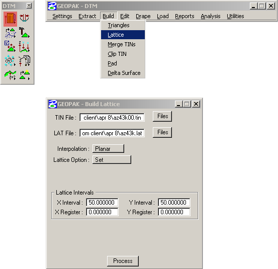
Choose the TIN file, then define a Lattice output file. There are a variety of Lattice Options which determine the grid cell size. The Set Option allows the direct definition of the grid size in master units. The register is the offset of the grid from the current coordinate system. Once the Lattice file is created, the file can be converted to DGN using the Load DTM Features tool shown above.
