3D MicroStation Files
Setup and Interface Tools
Roadway design files are typically 2D files in Microstation. Vizualizations of designs require the creation of 3D objects and 3D Microstation files. This section covers the creation of and navigation within 3D Microstation files.
Creating a 3D File
The easiest way to start working in 3D is to open an existing 3D file, or select New, and select the appropriate 3D seed file for your office. The recommended files for FLH are .... Microstation default seed files are under Bentley/Workspace/System/Seed, and the default file is seed3d.dgn.
A 2D file can be saved as a 3D file under a new name by using export under the file menu:
FILE>EXPORT>3D
Interface Tools
As in 2D files, viewports can be set up to display any desired view of a design file. In addition to standard 2D orthographic views, a 3D viewport can display in isometric; or in one, two or three-point perspective. A camera view is basically a three point perspective view. A camera view is defined with a position and a view direction, and view controls actually move the camera in 3D space. Cameras are discussed in more detail in Creating and Rendering Camera Views.
The View Control Toolbar is at the bottom left of each Viewport:

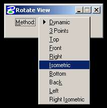
The Rotate View button allows a 3D change in view by rotating the view in different directions with the pointer. Rotate is a little different in a 3D view than in 2D. After selecting a viewport with a click, the view can be rotated in two directions simultaneously around the view center. Left to right pointer movement will cause rotation about the view Z axis, similar to rotation in a 2D drawing. Top to bottom mouse movement causes rotation about the view X axis. If the Dynamic Display box under Method is checked, geometry in the model will be updated in realtime as the scene is rotated. If the model is large, performance may suffer and the redraws will be very slow. If the box is unchecked, a 'cube' is temporarily drawn and rotated as the pointer is moved.
Pull down on the Method button, and any number of predefined views can be selected- including two isometric views. Isometric views are good starting points for 3D views. The view can then be altered by switching rotation back to Dynamic, and moving the pointer left/right and up/down.

Panning works the same in 3D as in 2D, except that in a 3D view the the pan will be relative to the view perspective, an isometric view will 'move' the view along the pan direction and remain in isometric.

The Window Area and Fit View options are very similar to 2D views, except that they also are relative to view perspective.
Active Depth
The active depth- the Z-value depth of the viewport, is set with the Set Active Depth on the View Control Toolbox. The toolbox is opened with:
TOOLS>VIEW CONTROL

Active depth is the planar level in the viewport at which new objects will be placed. Objects could be placed at a specific elevation by setting that elevation as the active depth in the top view. After pressing the button, select a viewport with a click, then select the depth in a perpendicular viewport (snap to an object at the right height), or the tool can be used with the Key-in function Active ZDepth Absolute, and a specific height can be typed in.
Saving Viewport Settings
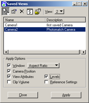
All of the settings for a view including view type, shading, and cameras can be saved out with the Saved Views option on the Utilities Menu:
UTILITIES>SAVED VIEWS

The utility saves a number of settings for each viewport including camera position, level settings, view size, etc. This is a great way to experiment with view positions. Previously saved views are available for reload. A sequence of views that show several angles of a design could be saved in one viewport's saved views, and be brought up one at a time for review, or loaded into multiple viewports for side by side comparison.
Just check the desired settings at the bottom of the dialog, then press the Save View button at the upper left. The dialog prompts for a view name and description.
