
Safety Eligibility Letter SS-172
Hardware Type:
Sign Supports, Mailboxes, and Delineator Posts
Code:
SS-172
Date:
Testing Criteria:
NCHRP 350
Manufacturer:
Dent Breakaway Industries, Inc.
Device Description:
Omni-Directional Dent Connector Assembly
View PDF:
ss172.pdf (280.65 KB)
Download Version
PDF [570 KB]
PDF [570 KB]

U.S. Department of Transportation
Federal Highway Administration
1200 New Jersey Ave. S.E.
Washington, D.C. 20590
June 23, 2011
In Reply Refer To: HSST/SS-172
Mr. Clifford M. Dent, President
Dent Breakaway Industries, Inc.
P.O. Box 6007
Farmington, NM 87499
Dear Mr. Dent:
This letter is in response to your request for the Federal Highway Administration (FHWA) acceptance of roadside safety systems for use on the National Highway System (NHS).
| Name of system: | Omni-Directional Dent Connector Assembly |
|---|---|
| Type of system: | Breakaway Connectors for Sign and Luminaire Supports |
| Test Level: | NCHRP Report 350 Test Level 3 |
| Testing conducted by: | Texas Transportation Institute |
| Date of request: | December 17, 2010 |
| Request acknowledged: | December 22, 2010 |
You requested that we find several variations of your tested Omni-directional Mechanical Dent Connector Assembly acceptable for use on the NHS under the provisions of the National Cooperative Highway Research Program (NCHRP) Report 350 “Recommended Procedures for the Safety Performance Evaluation of Highway Features.”
Requirements
Roadside safety devices should meet the guidelines contained in the National Cooperative Highway Research Program (NCHRP) Report 350 if tested prior to December 31, 2010, and the American Association of State Highway and Transportation Officials’ (AASHTO) Manual for Assessing Safety Hardware (MASH) if tested after that date. Requirements for breakaway supports are also contained in the AASHTO Standard Specifications for Structural Supports for Highway Signs, Luminaries, and Traffic Signals.
Decision:
The table below shows the five (5) sizes of your Omni-Directional Connector Assembly that were found acceptable and a drawing of the assembled design consisting of an upper and lower end section and an internal threaded connector rod:
| Bolt Name | ½” | 3/8” | ¼” | .380” | .280” |
|---|---|---|---|---|---|
| L1 MAX | 6” | 6” | 6” | 6” | 6” |
| L1 MIN | ¾” | ¾” | ¾” | ¾” | ¾” |
| L2 MAX | 6” | 6” | 6” | 6” | 6” |
| L2 MIN | ¾” | ¾” | ¾” | ¾” | ¾” |
| L3 | N/A | N/A | N/A | 1/8” | 1/8” |
| D1 MAX | 1” | 1” | 1” | 1” | 1” |
| D1 MIN | ¾” | 5/8” | ½” | ¾” | ¾” |
| D2 MAX | 1” | 1” | 1” | 1” | 1” |
| D2 MIN | ¾” | 5/8” | ½” | ¾” | ¾” |
| D3 | ½” | 3/8” | ¼” | ½” | ½” |
| D4 | N/A | N/A | N/A | .380” | .280” |
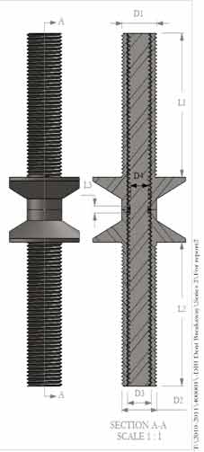
Description
The Omni-Directional Dent Connector is a three-piece assembly consisting of two end sections and a connecting rod. The end sections are fabricated from a hollow threaded rod with milled flanges at one end. Each is threaded on the outside to receive a 19-mm (3/4 inch) nut and washer and on the inside to receive the 13-mm diameter connecting rod.
Three variations of the Dent Connector were tested as described below. These variations were in the connecting rod only, using a solid 13 mm (1/2 inch) grade 5 threaded rod, and similar connecting rods milled at their midpoints to 0.280 inch and 0.380 inch diameters, respectively. When assembled, the milled sections were centered between the mated upper and lower flanges of the two end sections to form a shear plane.
Crash Testing
Pendulum testing was conducted on the test articles described above by the Texas Transportation Institute (TTI) at their outdoor pendulum testing facility.
For each test, the 1849-lb pendulum was set to impact the sign support system at a target impact speed of 22 mph and at a height of 18 inches above the ground (the bumper height of the small car). The three tests were conducted according to NCHRP 350 test designation 3-60.
In each test, a single post sign support system was tested. Tests P2 and P3 used a 3-m (10-ft) long HSS127×127×0.19-mm (HSS5×5×3/16-inch) post section supporting a 914×914×2.5-mm (36×36×0.1-inch) aluminum sign. Test P4 used a 3-m (10-ft) long 127-mm (5-inch) diameter schedule 40 steel post. A 257-mm (10-1/8-in) diameter, 19-mm (3/4-inch) thick base plate was welded to the bottom of each support post. A 203 mm (8-inch) hole pattern with four 22-mm (7/8-inch) bolt holes were drilled in each base plate to accept the 4 Dent Connectors.
For Test P2, the pendulum impacted the sign support with the 10-mm (0.380-inch) milled 13 mm (0.5 inch) grade 5 rods at a speed of 36.2 km/h (22.5 mph) at the desired height of 18 inches above ground level. The Dent Connectors sheared as designed and the support and sign panel came to rest 11.0 m (36 ft) downstream of the impact point. There was no damage to the Dent connectors or to the square tube support post, except for the milled connector rod. The sign panel remained connected to the sign post. The occupant impact velocity was 3.9 m/sec (12.8 ft/sec) and the calculated high-speed change in velocity was 2.4 m/sec (7.7 ft/sec), both below the NCHRP Report 350 maximum allowable value of 5.0 m/sec (16 ft/sec).
For Test P3, the milled connecting rods were replaced with 4 un-milled 13-mm (0.5-inch) grade 5 rods. This assembly was struck by the pendulum at 36.5 km/h (22.7 mph). As in Test P2, the Dent connector rods sheared as designed, and the sign and support came to rest 9.1 m (30 ft) downstream from the impact point. The occupant impact velocity was 4.1 m/sec (13.3 ft/sec) and the calculated high-speed change in velocity was 2.6 m/sec (8.4 ft/sec).
For Test P4, a schedule 40 steel support post was impacted by the pendulum at 36.2 km/h (22.5 mph). The 4 Dent connector rods used in this test were 7 mm (0.280-inch) milled 13 mm (0.5 inch) grade 5 rods. As in the previous tests, the Dent connector rods sheared as designed, and the sign and support came to rest 11.9 m (39 ft) downstream from the impact point. The occupant impact velocity was 2.5 m/sec (8.2 ft/sec) and the calculated high-speed change in velocity was 1.7 m/sec (5.6 ft/sec).
Findings
According to the NCHRP 350, test designation 3-60 and test designation 3-61 are to be conducted for support structures for Test Level 3 approval. In both tests full scale automobile testing with an 820C small car is required. However, the FHWA has sanctioned pendulum tests in lieu of the low-speed automobile test, at least for testing conducted prior to January 1, 2011. Thus, you conducted the three pendulum tests described above.
FHWA allows the results of the high speed tests to be estimated using data from the low-speed test in combination with an analytical extrapolation method described in the FHWA memorandum “Identifying Acceptable Highway Safety Features” dated on July 25, 1997. For all three test articles, the high speed test extrapolation analysis resulted in change in velocity values for the high speed tests below the NCHRP 350 limit of 5.0 m/s.
Due to the similarity in test results between your mechanical connector assembly and your previously-accepted milled design, you requested that previously approved applications remain valid when your mechanical connector rod design is substituted for your milled design. Please note that some conditions and limitations to the use of either design remain an effect, particularly the followings:
- All supports shall be mounted to a structural concrete foundation that will not move in the soil if the support is struck be a vehicle. Either your epoxy-embedded anchor or your embedded anchor with stabilizing plates may be used in the concrete footing to accept the Dent connector end section. Existing anchors, if undamaged in a crash, may also be used with your assembly.
- If used on dual supports closer than 2.1 m (7 feet) apart only the connecting rod with a 0.280 milled diameter may be used and the weight of the posts cannot exceed 27 kg/m (18 lbs/ft).
- The maximum diameter at the milled section of the connector rod is 0.280 inches for sign support legs up to 600 pounds with a maximum post size of 30 lbs/ft.
- Both your 0.280 and 0.380 milled connecting rods may be used with existing slip-base supports.
- Luminaire mounting height should not exceed 15.7 meters (55 feet).
- Mass of pole, mast arm, luminaire and other hardware above the couplings shall not exceed 454 kg (1000 lbs.).
Therefore, the system described above is acceptable for use on the NHS under the range of conditions tested, when such use is acceptable to a highway agency.
Please note the following standard provisions that apply to FHWA letters of acceptance:
- This acceptance is limited to the crashworthiness characteristics of the connector assemblies and does not cover their structural features, such as resistance to wind loads.
- Any design or material changes that may adversely influence the crashworthiness of the Dent system will require a new acceptance letter.
- Should the FHWA discover that the qualification testing was flawed, that in-service performance reveals unacceptable safety problems, or that the system being marketed is significantly different from the version that was crash tested, we reserve the right to modify or revoke our acceptance.
- You will be expected to supply potential users with sufficient information on design and installation requirements to ensure proper performance.
- You will be expected to certify to potential users that the hardware furnished has essentially the same chemistry, mechanical properties, and geometry as that submitted for acceptance, and that it will meet the crashworthiness requirements of the FHWA and the NCHRP Report 350.
- To prevent misunderstanding by others, this letter of acceptance is designated as number SS-172 and shall not be reproduced except in full. This letter and the test documentation upon which it is based are public information. All such letters and documentation may be reviewed at our office upon request.
- The Dent Connector Assemblies are patented products and considered proprietary. If proprietary systems are specified by a highway agency for use on Federal-aid projects, except exempt, non-NHS projects, (a) they must be supplied through competitive bidding with equally suitable unpatented items; (b) the highway agency must certify that they are essential for synchronization with the existing highway facilities or that no equally suitable alternative exists; or (c) they must be used for research or for a distinctive type of construction on relatively short sections of road for experimental purposes. Our regulations concerning proprietary products are contained in Title 23, Code of Federal Regulations, Section 635.411.
- This acceptance letter shall not be construed as authorization or consent by the FHWA to use, manufacture, or sell any patented system for which the applicant is not the patent holder. The acceptance letter is limited to the crashworthiness characteristics of the candidate system, and the FHWA is neither prepared nor required to become involved in issues concerning patent law. Patent issues, if any, are to be resolved by the applicant.
Sincerely yours, /* Signature of Michael S. Griffith */ Michael S. Griffith |