
Safety Eligibility Letter B-141F
Hardware Type:
Longitudinal Barriers and Bridge Rails
Code:
B-141F
Date:
Testing Criteria:
NCHRP 350
Manufacturer:
Trinity's Cable Safety System (CASS S3 4:1)
Device Description:
Four cable median and roadside barrier system
View PDF:
b141f.pdf (477.86 KB)
Safety Eligibility Letter B-141F
Download Version
PDF [478 KB]
PDF [478 KB]
![]()
U.S. Department of Transportation
Federal Highway Administration
1200 New Jersey Ave. S.E.
Washington, D.C. 20590
October 1, 2010
In Reply Refer To:
HSSD/B-141F
Mr. Brian Smith
Trinity Highway Products, LLC
P.O. Box 568887
Dallas, TX 75356-8887
Dear Mr. Smith:
This letter is in response to your request for the Federal Highway Administration (FHWA) acceptance of modifications to your CASS cable barrier safety system for use on the National Highway System (NHS).
Name of system: Trinity's Cable Safety System (CASS S3 4:1) Type of system: Four cable median and roadside barrier system Test Level: NCHRP Report 350:
Test Level 3 on 1:4 slopes or flatter
Test Level 4 on 1:6 slopes or flatterTesting conducted by: Texas Transportation Institute Date of request: March 5, 2010
You requested that we find this system acceptable for use on the NHS under the provisions of National Cooperative Highway Research Program (NCHRP) Report 350 "Recommended "
Requirements
Roadside safety systems should meet the guidelines contained in the NCHRP Report 350.
The FHWA memorandum "Identifying Acceptable Highway Safety Features" of July 25, 1997,
provides further guidance on crash testing requirements of longitudinal barriers.
Description
The CASS S3 4:1 is a tensioned, four-cable barrier system that was tested with standard (non-prestretched) cables. The top two cables are positioned within a wave-shaped slot in the
web of S75 x 8 (S3 x 5.7 in English units) structural I-beam posts. The bottom two cables are supported on flanges of the I-beam post by an 8-mm (5/16-inch) hook bolt with the open end down, with the lowest cable located on the median-side flange and the next lowest cable located
on the traffic-side flange.
The proprietary S75 × 8 (S3 × 5.7) posts were installed in steel tube sleeves set in 305-mm (12-inch) diameter x 762-mm (30-inch) deep concrete footings. The cables within the wave-shaped slot are separated by a plastic spacer. A stainless steel strap is mounted on the outside of the post above the top cable.
The 3/4-inch diameter standard (non-pre-stretched) cables were set at heights of 450mm, 755mm, 960 and 1070mm (17.75, 29.75, 37.875, and 42.125 inches) above the ground surface, measured to the center of each cable. Tension of the cables was set at 24.9 kN (5,600 pounds
force) for the tests.
The 104.7-m (343-foot, 6-inch) test installations were anchored by Texas Transportation Institute (TTI) Breakaway Cable Anchor Terminals which were accepted by the FHWA on August 29, 2002.
Four tests were conducted with the CASS S3 4:1 system installed in a 9.1m (30 foot 0 inch) wide depressed median with 1V: 4H side slopes, and one test with the CASS S3 4:1 system installed on level terrain:
-
The NCHRP Report 350 Test 3-11 (modified) - 2270P at 102.6 km/hour (63.7 mph) with a 25.4 degree impact angle. The test article was the CASS S3 4:1 with 3.2-m (10-foot, 6-inch) post spacing installed on the foreslope of a 9.1-m (30-foot, 0-inch) wide depressed median with 1V: 4H side slopes at 1.22m (4 foot, 0 inch) from the break point.
The CASS S3 4:1 on 1V:4H foreslope contained and redirected the 2270P vehicle. The vehicle did not penetrate, under ride, or override the installation. Dynamic deflection in Test 3-11 (modified) with 3.2-m (10-foot, 6-inch) post spacing was reported by TTI to be 2.16m (7.1 feet).
-
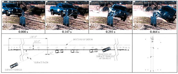
The NCHRP Report 350 Test 3-10 - 820C at 102.1 km/hour (63.4 mph) with a 20.8 degree impact angle. The test article was the CASS S3 4:1 with 6.1-m (20-foot, 0-inch) post spacing installed on the backslope of the 9.1-m (30-foot, 0-inch) wide depressed median at 3.35m (11 feet 0 inch) from the median bottom. The test vehicle crossed the median bottom and traveled up the backslope before impacting CASS S3 4:1.
The CASS S3 4:1 on 1V:4H backslope contained the 820C vehicle, which then sideslipped along the system until loss of contact. The vehicle did not penetrate, under ride, or override the installation. Dynamic deflection in Test 3-10 (backslope) with 6.1-m (20-foot, 0-inch) post spacing was reported by TTI to be 1.34m (4.4 feet).
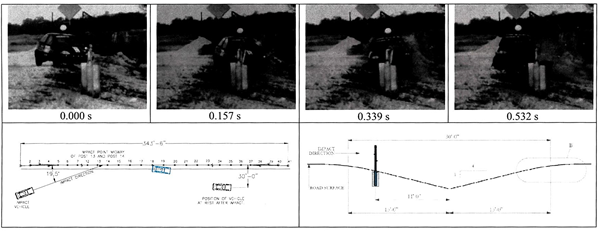
The NCHRP Report 350 Test 3-10 - 820C at 97.3 km/hour (60.4 mph) with a 19.5 degree impact angle. The test article was the CASS S3 4:1 with 3.2-m (10-foot, 6-inch) post spacing installed on the foreslope of a 99.1-m (30-foot, 0-inch) wide depressed median with 1V: 4H side slopes at 1.22m (4 foot, 0 inch) from the break point.
The CASS S3 4:1 on 1V:4H foreslope contained and redirected the 820C vehicle. The vehicle did not penetrate, under ride, or override the installation. Dynamic deflection in Test 3-10 with 3.2-m (10-foot, 6-inch) post spacing was reported by TTI to be 1.04m (3.4 feet).
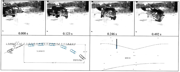
The NCHRP Report 350 Test 3-11 (modified) - 2270P at 102.4 km/hour (63.6 mph) with a 25.4 degree impact angle. The test article was the CASS S3 4:1 with 6.4-m (21-foot, 0-inch) post spacing installed on the foreslope of a 9.1-m (30-foot, 0-inch) wide depressed median with 1V: 4H side slopes at 1.22m (4 foot, 0 inch) from the break point.
The CASS S3 4:1 on 1V:4H foreslope contained and redirected the 2270P vehicle. The vehicle did not penetrate, under ride, or override the installation. Dynamic deflection in Test 3-11 (modified) with 6.4-m (21-foot, 0-inch) post spacing was reported by TTI to be 2.59m (8.5 feet).
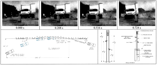
The NCHRP Report 350 Test 4-12 - 8000S at 79.9 km/hour (49.6 mph) with a 13.6 degree impact angle. The test article was the CASS S3 4:1 with 3.2-m (10-foot, 6-inch) post spacing installed on level terrain.
The CASS S3 4:1 on flat ground contained and redirected the 8000S vehicle. The vehicle did not penetrate, under ride, or override the installation. Dynamic deflection in Test 4-12 with 3.2-m (10-foot, 6-inch) post spacing was reported by TTI to be 2.42m (8.0 feet).
The 4-cable barrier systems described above are acceptable for use on the designated 1V:4H or flatter slopes under NCHRP Report 350 Test Level 3 or 4 conditions as noted. The systems are detailed in the enclosed drawings and are acceptable for use on the NHS when such use is
Findings
The 4-cable barrier systems described above are acceptable for use on the designated 1V:4H or flatter slopes under NCHRP Report 350 Test Level 3 or 4 conditions as noted. The systems are detailed in the enclosed drawings and are acceptable for use on the NHS when such use is acceptable to a highway agency.
Although the barrier performed well under idealized test impact conditions, the likelihood of passenger car underrides of any cable system may increase as the post spacing increases, particularly when the barrier is installed on non-level or slightly irregular terrain and the cables are not restrained from lifting at each post. Consequently, some transportation agencies have limited post spacing to approximately 6m (20 feet) for cable barriers. The dynamic deflection of the barrier is likely to increase when it is installed along the convex sides of horizontal curves,
Please note the following standard provisions that apply to FHWA letters of acceptance:
- This acceptance is limited to the crashworthiness characteristics of the systems and does not cover their structural features, nor conformity with the Manual on Uniform Traffic Control Devices.
- Any changes that may adversely influence the crashworthiness of the system will require a new acceptance letter.
- Should the FHWA discover that the qualification testing was flawed, that in-service performance reveals unacceptable safety problems, or that the system being marketed is significantly different from the version that was crash tested, we reserve the right to modify or revoke our acceptance.
- You will be expected to supply potential users with sufficient information on design and installation requirements to ensure proper performance.
- You will be expected to certify to potential users that the hardware furnished has essentially the same chemistry, mechanical properties, and geometry as that submitted for acceptance, and that it will meet the crashworthiness require of the FHWA and the NCHRP Report 350.
- To prevent misunderstanding by others, this letter of acceptance is designated as number B-141F and shall not be reproduced except in full. This letter and the test documentation upon which it is based are public information. All such letters and documentation may be reviewed at our office upon request.
- The CASS barriers are patented products and considered proprietary. If proprietary systems are specified by a highway agency for use on Federal-aid projects, except exempt, non-NHS projects, (a) they must be supplied through competitive bidding with equally suitable unpatented items; (b) the highway agency must certify that they are essential for synchronization with the existing highway facilities or that no equally suitable alternative exists: or (c) they must be used for research or for a distinctive type of construction on relativdy short sections of road for experimental purposes. Our regulations concerning proprietary products are contained in Title 23, Code of Federal Regulations, Section 635.411.
- This acceptance letter shall not be construed as authorization or consent by the FHWA to use, manufacture. or sell any patented system for which the applicant is not the patent holder. The acceptance letter is limited to the crashworthiness characteristics of the candidate system and the FHWA is neither prepared nor required to become involved in issues concerning patent law. Patent issues, if any, are to be resolved by the applicant.
Sincerely yours, /* Signature of David A. Nicol */ David A. Nicol, P.E. |
Enclosures
| General Information | Impact Conditions | Post-Impact Trajectory | |||
| Test Agency | Texas Transportation Institute | Speed | 49.6 mi/h | Stopping Distance | 348 ft dwnstrm 46 ft twd traffic |
| Test No. | 400001-TCR33 | Angle | 13.6 degrees | Vehicle Stability | |
| Date | 2009-09-04 | `Location/Orientation | 1 ft upstream | Maximum Yaw Angle | -23 degrees |
| Test Article | Exit Conditions | Post 16 | Maximum Pitch Angle | -3 degrees | |
| Type | Longitudinal Barrier | Speed | Not obtainable | Maximum Roll Angle | 1 degrees |
| Name | Trinity CASS | Angle | Not obtainable | Vehicle Snagging | No |
| Installation Length | 343.5 ft. | Occupant Risk Values | Vehicle Pocketing | No | |
| Material or Key Element | 4 wire ropes supported by slotted S3x5.7 support posts spaced at 10 ft-6 inches | Impact Velocity | Test Article Deflections | ||
| Soil Type and Condition | Concrete footings in crushed limestone, dry | Longitudinal | 3.6 ft/s | Dynamic | ~8 ft |
| Test Vehicle | Lateral | 4.9 ft/s | Permanent | 0.9 ft | |
| Type/Designation | 8000s | Ridedown Accelerations | |||
| Make and Model | 1994 International NaviStar 4700 | Longitudinal | -1.4 G | Working Width | 9.1 ft |
| Curb | 12,400 lb | Lateral | -1.3 G | Vehicle Damage | |
| Test Inertial | 17,710 lb | THIV | 6.4 km/h | VDS | 01RFQ1 |
| Dummy | No dummy | PHD | 0.12 | CDC | 01RFEW1 |
| Gross Static | 17,710 lb | Max. 0.050-s Average | Max. Exterior Deformation | 1.5 inches | |
| Longitudinal | -06.g | Max. Exterior Deformation | 1.5 inches | ||
| Lateral | -1.1G | ||||
| Vertical | 0.4 G | ||||
Figure 15. Summary of results for NCHRP Report 350 test 4-12 on the Trinity CASS on level ground.
| General Information | Impact Conditions | Post-Impact Trajectory | |||
| Test Agency | Texas Transportation Institute | Speed | 60.4 mi/h | Stopping Distance | 214 ft dwnstrm 30 ft twd traffic |
| Test No. | 400001TCR35 | Angle | 19.5 degrees | Vehicle Stability | |
| Date | 2009-10-08 | Location/Orientation | Midspan btw posts 15&16 | Maximum Yaw Angle | 32 degrees |
| Test Article | Exit Conditions | Maximum Pitch Angle | 9 degrees | ||
| Type | Cable Barrier | Speed | Not obtainable | Maximum Roll Angle | 14 degrees |
| Name | Trinity CASS | Angle | -3.6 degrees | Vehicle Snagging | No |
| Installation Length | 343.5 ft. | Occupant Risk Values | Vehicle Pocketing | No | |
| Material or Key Element | CASS with S3x5.7 posts installed on 4H:1V forslope | Impact Velocity | Test Article Deflections | ||
| Soil Type and Condition | Concrete footings in Standard Soil, Damp | Longitudinal | 12.8 ft/s | Dynamic | 3.4 ft |
| Test Vehicle | Lateral | 12.8 ft/s | Permanent | 0.1 ft | |
| Type/Designation | 820C | Ridedown Accelerations | Working Width | 4.2 ft | |
| Make and Model | 1995Suzuki Swift | Longitudinal | -5.3G | Vehicle Damage | |
| Curb | 1881 lb | Lateral | 6.3 G | VDS | 11LFQ3 |
| Test Inertial | 1850 lb | THIV | 18.2 km/h | CDC | 11FDEW3 |
| Dummy | 167 | PHD | 7.5 G | Max. Exterior Deformation | 10.6 inches |
| Gross Static | 2017 lb | Max. 0.050-s Average | Max.Occupant Compartment Deformation | 0.6 inches | |
| Longitudinal | -2.9 G | ||||
| Lateral | 4.3 G | ||||
| Vertical | 3.7 G | ||||
Figure 16. Summary of results for NCHRP Report 350 test 3-10 on the Trinity CASS with S3x5.7 posts installed on a 4H:IV forslope.
| General Information | Impact Conditions | Post-Impact Trajectory | |||
| Test Agency | Texas Transportation Institute | Speed | 63.7 mi/h | Stopping Distance | 425 ft dwnstrm 83 ft twd traffic |
| Test No. | 40000-1TCR32 | Angle | 25.4 degrees | Vehicle Stability | |
| Date | 2009-08-12 | Location/Orientation | At post 16 | Maximum Yaw Angle | 39 degrees |
| Test Article | Exit Conditions | Maximum Pitch Angle | -6 degrees | ||
| Type | Longitudinal Barrier | Speed | Out of view | Maximum Roll Angle | 28 degrees |
| Name | CASS on 4H:1V Slope | Angle | Not obtainable | Vehicle Snagging | No |
| Installation Length | 343.5 ft. | Occupant Risk Values | Vehicle Pocketing | Yes | |
| Material or Key Element | CASS with S3x5.7 posts spaced at 10ft-6 inches on 4V:H1 forslope | Impact Velocity | Test Article Deflections | ||
| Soil Type and Condition | Cruch Limestone, Dry | Longitudinal | 8.2 ft/s | Dynamic | 7.1 ft |
| Test Vehicle | Lateral | 13.4 ft/s | Permanent | 0.5 ft | |
| Type/Designation | 2270P | Ridedown Accelerations | Working Width | 8.2 ft | |
| Make and Model | 2003 Dodge 1500 Quad | Longitudinal | -3.5G | Vehicle Damage | |
| Curb | 4871 | Lateral | 4.3 G | VDS | 11LFQ1 |
| Test Inertial | 5007 | THIV | 15.9 km/h | CDC | 11LFEW2 |
| Dummy | No Dummy | PHD | 5.0 G | Max. Exterior Deformation | 10.6 inches |
| Gross Static | 5007 | Max. 0.050-s Average | Max.Occupant Compartment Deformation | 0 | |
| Longitudinal | -2.0 G | ||||
| Lateral | 3.5 G | ||||
| Vertical | -2.9 G | ||||
Figure 11. Summary of results for NCHRP Report 350 test 3-11 on CASS with S3x5.7 posts on 4H:IV forslope.
| General Information | Impact Conditions | Post-Impact Trajectory | |||
| Test Agency | Texas Transportation Institute | Speed | 63.6 mi/h | Stopping Distance | 73.5 ft dwnstrm Within cables |
| Test No. | 400001-TCR32 | Angle | 25.4 degrees | Vehicle Stability | |
| Date | 2009-11-08 | Location/Orientation | At post 13 | Maximum Yaw Angle | 32 degrees |
| Test Article | Exit Conditions | Maximum Pitch Angle | -12 degrees | ||
| Type | Wire Rope Barrier | Speed | Out of view | Maximum Roll Angle | -57 degrees |
| Name | CASS with S3x5.7 posts/4H:1V foreslope | Angle | Out of view | Vehicle Snagging | No |
| Installation Length | 343.5 ft. | Occupant Risk Values | Vehicle Pocketing | No | |
| Material or Key Element | CASS with S3x5.7 posts installed 4V:1V forslope | Impact Velocity | Test Article Deflections | ||
| Soil Type and Condition | Standard Soil, Dry | Longitudinal | 8.8 ft/s | Dynamic | 8.5 ft |
| Test Vehicle | Lateral | 12.5 ft/s | Permanent | 3.0 ft | |
| Type/Designation | 2270P | Ridedown Accelerations | Working Width | 9.8 ft | |
| Make and Model | 2004 Dodge Ram1500 Quad-Cab | Longitudinal | -4.1G | Vehicle Damage | |
| Curb | 4772 lb | Lateral | 5.9 G | VDS | 11LFQ2 |
| Test Inertial | 5026 lb | THIV | 15.2 km/h | CDC | 11DEW2 |
| Dummy | No Dummy | PHD | 6.1 G | Max. Exterior Deformation | 7.5 inches |
| Gross Static | 5026 lb | Max. 0.050-s Average | Max.Occupant Compartment Deformation | 0 | |
| Longitudinal | -2.0 G | ||||
| Lateral | 3.6 G | ||||
| Vertical | -1.8 G | ||||
Figure 16. Summary of results for NCHRP Report 350 test 3-11 on the CASS with S3x5.7 posts installed on 4H:IV forslope.
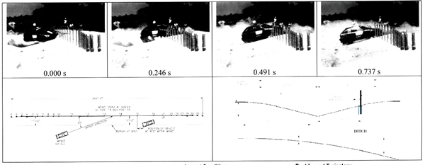
| General Information | Impact Conditions | Post-Impact Trajectory | |||
| Test Agency | Texas Transportation Institute | Speed entering ditch | 63.4 mi/h | Stopping Distance | 35 ft dwnstr 11 ft field side |
| Test No. | 40000-1TCR34 | Angle entering ditch | 20.8 degrees | Vehicle Stability | |
| Date | 2009-10-12 | Speed at wire rope | 60.8 mi/h | Maximum Yaw Angle | -172 degrees |
| Angle at wire rope | 24.0 degrees | ||||
| Location/Orientation | Mispan 13-14 | ||||
| Test Article | Exit Conditions | Maximum Pitch Angle | 26 degrees | ||
| Type | Median Barrier | Speed | Out of view | Maximum Roll Angle | -34 degrees |
| Name | Trinity CASS | Angle | Out of view | Vehicle Snagging | Yes |
| Installation Length | 342 ft. | Occupant Risk Values | Vehicle Pocketing | No | |
| Material or Key Element | S3x5.7 posts installed on a 4H:1V backslope | Impact Velocity | Test Article Deflections | ||
| Soil Type and Condition | Concrete footings in standard soil, damp | Longitudinal | 18.7 ft/s | Dynamic | 4.4 ft |
| Test Vehicle | Lateral | 2.3 ft/s | Permanent | 1.9 ft | |
| Type/Designation | 820C | Ridedown Accelerations | Working Width | 5.2 ft | |
| Make and Model | 1997 Geo Metro | Longitudinal | -8.9 G | Vehicle Damage | |
| Curb | 1797 lb | Lateral | -8.6 G | VDS | 11LFQ4 |
| Test Inertial | 1861 lb | THIV | 19.2 km/h | CDC | 11FLEW3 |
| Dummy | 165 lb | PHD | 11.9 G | Max. Exterior Deformation | 9.8 inches |
| Gross Static | 2026 lb | Max. 0.050-s Average | Max.Occupant Compartment Deformation | 1.2 inches | |
| Longitudinal | -7.8G | ||||
| Lateral | -4.4 G | ||||
| Vertical | -5.4 G | ||||
Figure 15. Summary of results for NCHRP Report 350 test 3-10
on the Trinity CASS with S3x5.7 posts installed on a 4H:IV backslope.