Hydraulics Laboratory Zones
Zone 1 – Multifunctional Flume System (MFS)
Zone 2 – Force Balance Fume System (FBF)
Zone 3 – In situ Scour Testing Device (ISTD) – Lab Drill Rig
Zone 4 – Lab Soil Erosion Testing Devices
Zone 5 – Particle Image Velocimetry (PIV), Lasers, and Cameras
Zone 6 – Laboratory Office and 3D Printing
Zone 7 – Laboratory Machine Shop
Zone 1 – Multifunctional Flume System (MFS)
The MFS features a 90-foot-long by 13-foot-wide tiltable working platform for experimental setups. Channel sections of 3- or 6-foot wide can be mounted on the working deck. Both channel section alternatives include a 27-foot-long sediment recess test section. If needed, other hydraulic structures such as culverts, pipes, and drainage systems can be installed and tested. The flume system also includes a 27-foot-long flow inlet headworks and a carefully designed outlet section that includes a sediment trap. The sediment recirculating system, which is the only one of its kind in the United States, consists of an inclined auger, conveyor belt, and sediment infeed hopper. Diaphragm pumps push sediment from the infeed hopper into the flume through computationally-optimized and 3D-printed infeed nozzles located at the bottom of a specially-designed channel section. This sediment recirculation capability allows for much more realistic river flow modeling. The pump discharge capacity of the MFS is 30 cubic feet per second (ft3/s). An automated instrumentation carriage and industrial robot carriage system hold sensors needed to measure flow and sediment transport/scour data, and to assist with the setup of experiments. The main purpose of the experiments in the MFS is to calibrate computational fluid dynamics (CFD) models for further analysis and development of guidelines.
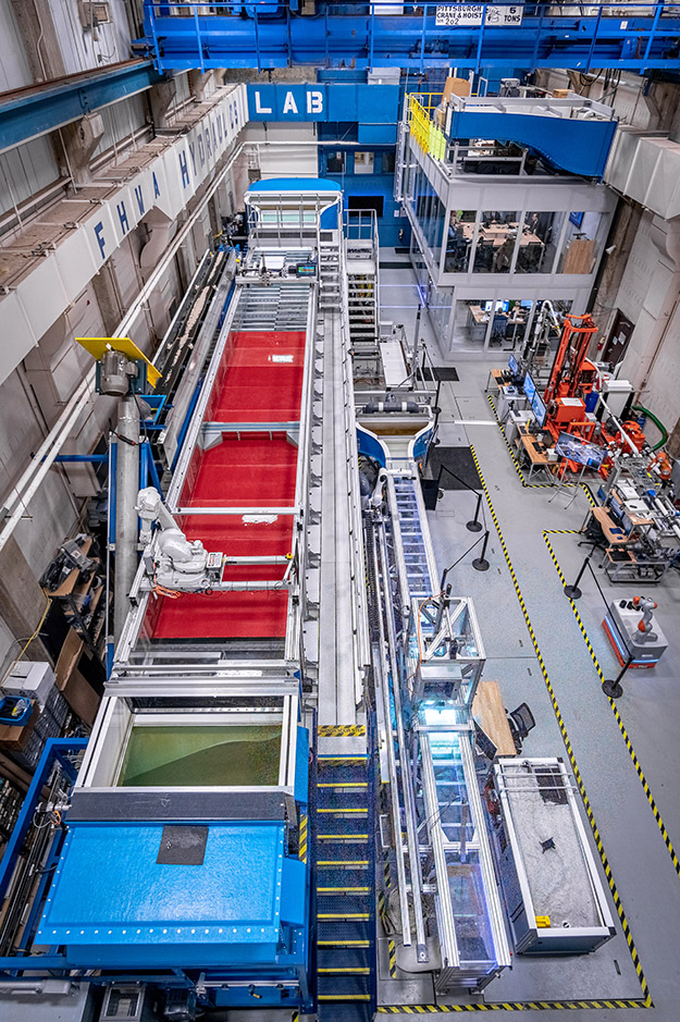
Figure 1. Elevated view of the MFS (Click to view larger image).
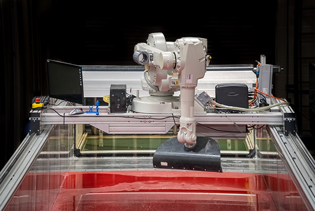
Figure 2. View of the MFS’s industrial robot carriage system (Click to view larger image).
Zone 2 – Force Balance Flume System (FBF)
The force balance flume is 36 feet long and 15 inches wide. In this configuration, a discharge rate of over 3 ft3/s can be achieved. An industrial robotic arm is utilized on the FBF to hold sensors for measuring flow properties and to act as a temporary force balance for the study of hydrodynamic loads on structures until a new force balance tower is installed. The proposed force balance tower will also be used to study hydraulic erosion forces on 3D-printed bridge foundation scour forms. The main purpose of the FBF is to perform high-precision force measurement experiments to calibrate CFD simulations. The goal of these experiments is researching and analyzing hydrodynamic loads/forces responsible for scour and erosion around bridge foundations in order to improve scour prediction estimates for the new scour design vision.
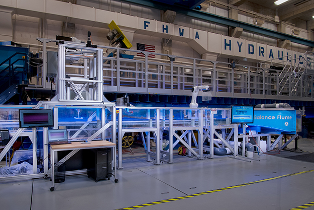
Figure 3. The Force Balance Flume in the Hydraulics Lab (Click to view larger image).
Zone 3 – In-situ Scour Testing Device (ISTD) – Lab Drill Rig
The ISTD is an advanced system designed to measure the erosion resistance of fine-grained cohesive soils directly in the field. It features an innovative erosion head that, when inserted into a standard drill casing, can direct a horizontal radial flow across the surface of the soil resulting in erosion. The erosion resistance is measured in terms of a critical shear stress, which when coupled with the decay of hydraulic shear with scour depth, is the basis of FHWA's new scour vision for improving the accuracy of future bridge scour estimates.
The lab hosted a series of field demonstrations in States across the country to promote the technology and improve the ISTD system's technology readiness level. A photo showing the typical layout of the equipment at a demonstration is shown in figure 4.
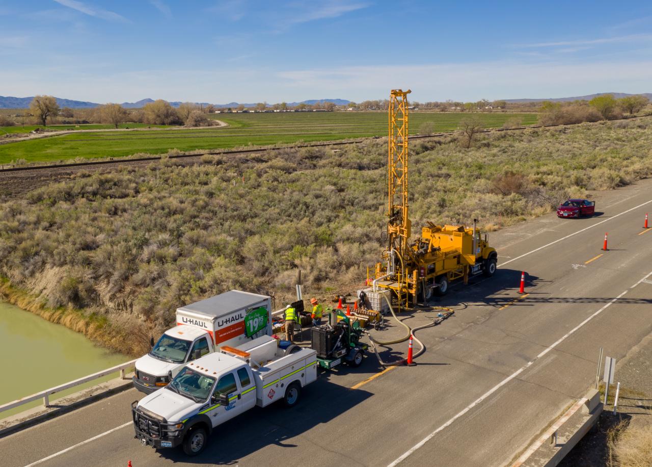
Figure 4. The setup of the ISTD equipment in the field for a demonstration.
A simplified “portable” scour testing device (PSTD) was recently developed in the lab and introduced to the field demonstrations that allows the tests to be conducted at ground level in a reduced footprint to improve testing efficiency.
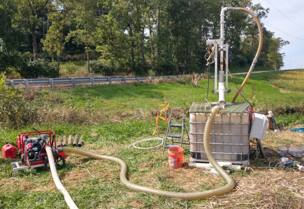
Figure 5. The simplified PSTD setup in the field. (Click to view larger image.)
Zone 4 – Lab Soil Erosion Testing Devices
Multiple devices and tools are utilized in this laboratory zone including the ex-situ scour testing device laboratory (ESTD) and various soil preparation and geotechnical testing apparatuses.
Soil Compaction Station
The soil compaction station reproduces lab soil samples that have similar strength to field soils. An intelligent industrial robot featuring a 7-axis robotic arm and mobile platform is programmed to carry soil samples between the compaction station and the various testing devices while utilizing sensors to avoid obstacles.
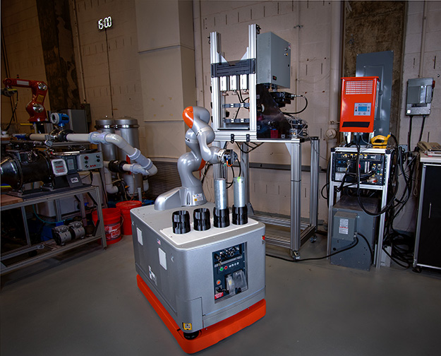
Figure 6. An industrial robot prepares to place soil samples in the compaction station.
Ex-Situ Scour Testing Device (ESTD)
The ESTD measures the erodibility of a cylindrical soil specimen under well-controlled flow conditions. It has an overall dimension of 15-feet long, 6-feet wide, and 5.3-feet high. Its rectangular testing channel has a dimension of 3-feet long, 4.7-inch wide, and 0.75-inch high. The maximum flow rate in the ESTD is 0.5 ft3/s, which translates to a maximum average flow speed of 20 ft/s in the testing channel. The ESTD features an innovative shear stress sensor that can instantaneously measure the bed shear stress during the erosion process. The system can accommodate a 1-foot-long field soil sample in a Shelby tube with a 3-inch outer diameter. The soil can be automatically pushed up by a hydraulic piston as the erosion progresses. The extrusion is controlled by quasi-instantaneous detection of the soil surface change using an underwater laser scanner held by an industrial robot.
Soil erosion resistance testing is a part of the new scour design vision and is needed to determine the scour depth limit state. The vision of zone 4 is to develop and demonstrate a fully automated soil erosion resistance testing laboratory which utilizes a robotic assembly line that can be deployed in the field.
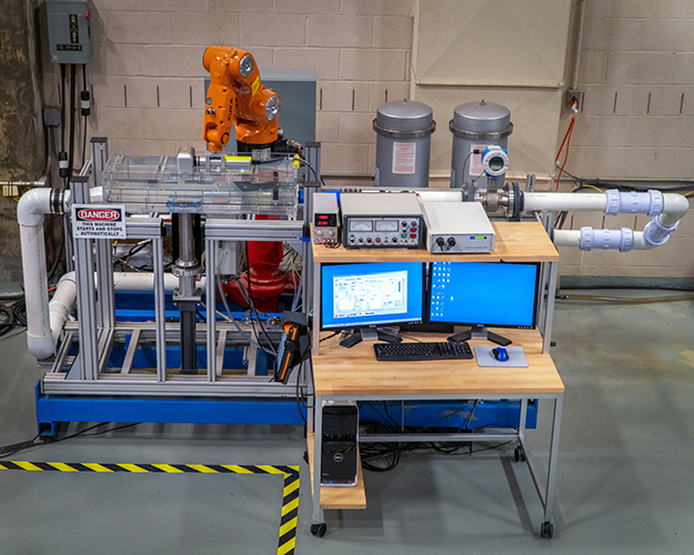
Figure 7. The ex-situ scour testing device (ESTD).
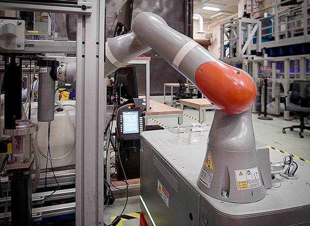
Figure 8. The robot inserts a soil sample into the ESTD.
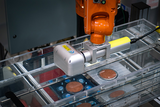
Figure 9. The laser scanner measuring the surface of a soil sample in the ESTD.
Zone 5 – Particle Image Velocimetry (PIV), Lasers, and Cameras
Particle Image Velocimetry (PIV) is an optical method of flow visualization used for many research activities in the Hydraulics Laboratory. It is used to obtain instantaneous velocity measurements and related flow properties. The flow is seeded with tracer particles that, for sufficiently small particles, are assumed to faithfully follow the flow dynamics. The flow with entrained particles is illuminated so that particles are visible. The motion of the seeding particles is used to calculate speed and direction (the velocity field) of the flow being studied.
The Hydraulics Laboratory's PIV system can be used for 2D-2 Components and 2D-3 Components Time Resolved PIV (TPIV). The Laboratories Litron LPY laser has a pulse energy of 50mJ and consists of two parallel laser systems, each capable of creating 200 pulses per second, that allow for the usage of TPIV. Special laser optics can create light sheets that are from 1- to 3-mm thick, illuminating the cross section of the flow that needs to be visualized. Hollow glass spheres (with a diameter of 10 to 110 microns) covered with silver oxide are used as tracer particles. High-speed cameras are utilized to detect the motion of the particles and to measure the velocity flow field.
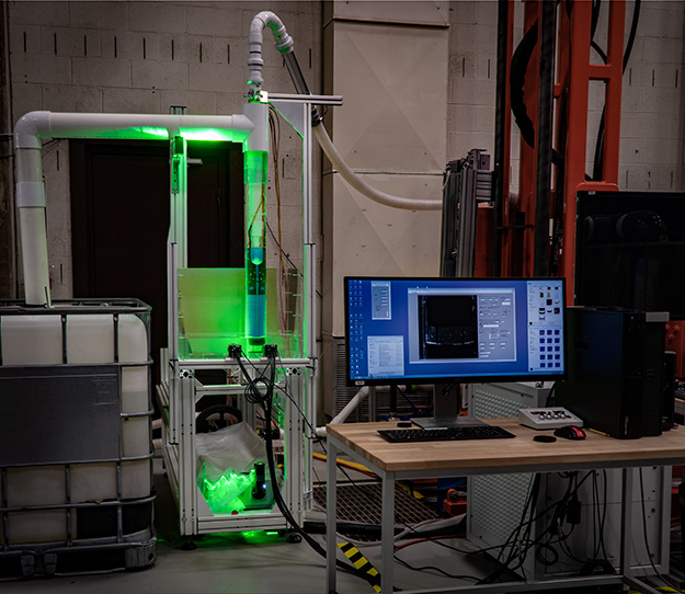
Figure 10. The Litron LPY laser illuminating the ISTD erosion head for a PIV experiment.
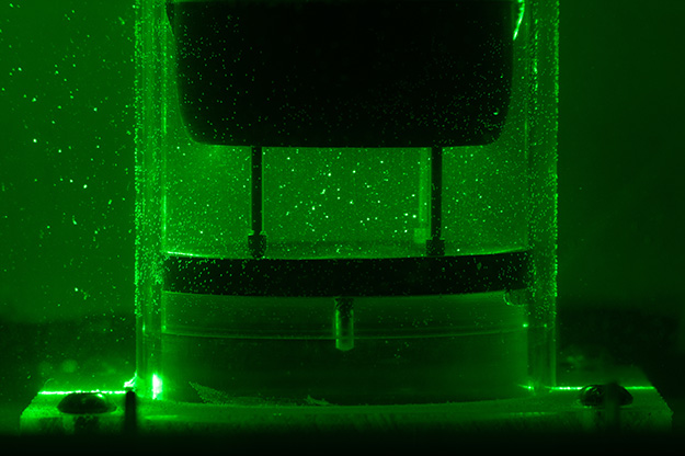
Figure 11. Tracer particles around the erosion head allow for flow visualization.
Zone 6 – Laboratory Office and 3D Printing
The Laboratory has a new state-of-the-art office designed as a collaboration and modeling space for the lab personnel. The second floor includes an advanced computing center where experienced CFD specialists prepare computer simulations that are then sent to Argonne National Laboratory’s (ANL’s) Transportation Analysis Research Computing Center (TRACC), where multicore clusters run the simulations. A conference room for collaborative discussions is on the second floor. An Advanced Engineering Hub is where lab personnel perform calculations and work immersed in the lab environment with noise- and climate-control to optimize performance. Multiple 3D printers are located both on the first and second floors of the office. These printers are utilized to create bridge models, sensor mounts, presentation models, and other essential functions.
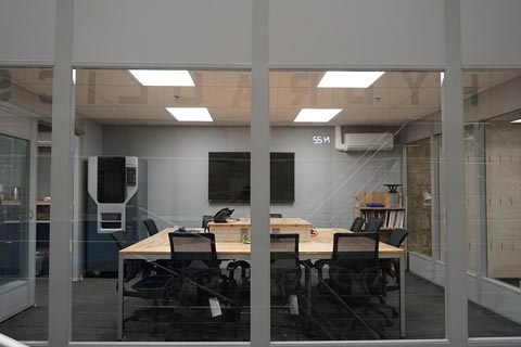
Figure 12. Lab conference room with Fortus 3D printer in far-left corner.
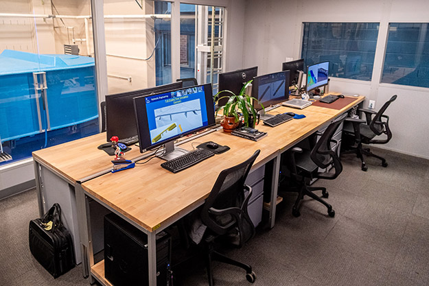
Figure 13. Advanced Computing Center.
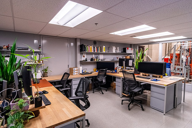
Figure 14. Advanced Engineering Hub.
Zone 7 – Laboratory Machine Shop
The Laboratory also has its own machine shop where various tools can be accessed. Basic tools such as Allen wrenches, pliers, fasteners, screws, etc., are stored here. Additionally, the machine shop is equipped with multiple milling machines and various saws that can be utilized to prepare experiments and build structures. A new addition to the machine shop is a state-of-the-art laser cutter that is being used to help prepare bridge models as well as precisely resized and shape compatible materials.
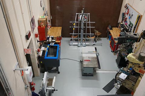
Figure 15. Laboratory Machine Shop.

